 TADPRO - Torque and Drag Model
- Overview
- Features
- Resources
- Specification
Today’s more prevalent extended-reach directional wells mean that tubulars are exposed to greater amounts of torque and drag (T&D). If this torque and drag is not evaluated, this can result in stuck pipe, pipe failures, and costly fishing jobs.
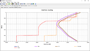
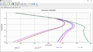
TADPRO, the most comprehensive torque and drag software in the market, removes many of the risks of a drilling program, completion design or specific tool operation. Limits in the length of a horizontal based on specific friction factors can be determined. The ability to get needed weight to a liner-top packer can also be evaluated. With the ability to analyze forces downhole, rig equipment specifications for torque and hookload can be predicted.
With unparalleled user-friendliness and graphical outputs in the industry, TADPRO provides both versatility and accuracy in its calculations. The software also integrates advanced features that make it extremely easy to use and allow results to be interpreted effortlessly.
- Torque, drag and stress calculation
- Soft and stiff string models
- Drilling, back reaming, rotation off bottom, tripping in and tripping out operations
- Sinusoidal and helical buckling prediction
- Field data comparison on hookload and surface torque
- Friction factor sensitivity analysis
- Friction factor calibration
- Packer setting analysis
- Casing flotation
- Swivel tool
- Oscillating vibration tool
- Torque and drag calculation on cementing job
- Survey import from Excel®, text or PDF® file
- Survey tortuosity
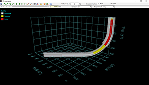
- 2D/3D animation
- Graph customization
- Microsoft Word® report
- US oil field, SI and customized units
- Multi-language: English, Spanish, Chinese, Russian and Portuguese
- Screenshots
- Brochures
- White Paper
- FAQ
- Bookstore
Q1. How are friction factors (FFs) defined in TADPRO?
FFs are defined in Wellbore Interval table. Cased hole friction factors (CHFFs) and open hole friction factors (OHFFs) are defined separately. These are user defined values, though recommended values are accessible using the quick help feature next to the FF portion of the table (the question mark button).
For sections of the string that have tools or centralizers, the friction factor might be reduced or changed. This can be accounted for at the bottom of the detailed table for each component by using a percent friction reduction.
If the tools/centralizers are free to rotate relative to the string, the rotational FF is used to calculate torque instead of the values listed in the wellbore intervals table.
Q2. What is the calculation interval option?
It defines the locations of string bottom where the torque and drag profile is calculated. The smaller the calculation interval, the longer the calculation time.
The calculation interval simply determines how often points are calculated/placed in the history graphs. History graphs are hook load and surface torque, as well as stretch and twist graphs. The default interval is 100 ft, though smaller intervals can be chosen to increase the accuracy or smoothness of the history graphs. Since a full set of profile tables/graphs (side force/axial force/torque) are needed for each point placed in a history graph, choosing a small calculation interval can increase the required calculation time.
Q3. What is the “Calculation on survey points” option?
T&D software calculates in small segments and cumulatively sums the results, beginning at the bottom of the string and working up to the surface. Choosing the ‘calculate on survey points’ option will set the segment length to the distance between survey points, as reflected in the survey. Surveys with a 100 ft interval for a 15,000 ft well would result in 150 separate sections over which torsional and axial forces are determined.
For each string bottom location, in order to calculate torque and drag, the pipe is divided into many elements. Each component should have the same mud weight, wellbore size, pipe geometry and dogleg. Calculation on survey points ensures the same dogleg in each component.
Q4. What does the “Calculate torque and drag without FF reduction” option do?
This will run an automated comparison between the T&D model as set up and the T&D model without friction reduction applied. The without friction reduction T&D model affects the pipe tab only by setting the ‘FF reduction’ to zero and the tool/centralizer ‘free to rotate’ box to unchecked for all pipe components.
Q5. What is the side force normalization length, and how does it affect side force?
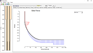
Side force is calculated as a force per distance (i.e. lb/ft). The normalization length simply multiplies the force per unit distance by a length. The normalization length does not affect the calculations, but rather the numbers displayed in the side force graph. At 100 lb/ft, a normalization length of 31 ft would show 3,100 lbs in the graph vs. a normalization length of 40 ft resulting in 4,000 lbs on that same graph.
When the side force is set to ‘per joint’, the normalization length will default to the joint length for each pipe component. It is therefore possible to have the side force normalized for different length components in the same graph, such as 31 ft for drill pipe and 40 ft for casing/liner.
-

Trouble-Free Drilling - $125
, published by Drilbert Engineering, Inc., 2003
This 280-page reference manual containing over 200 full-color illustrations. This best-selling manual is one of the most comprehensive works available on the physics pertaining to the problem of stuck pipe. Written in an easy-to-understand, and entertaining format, Trouble-Free Drilling is an invaluable tool for rig-site supervisors, drillers, and drilling engineers.
For a limited time, a complimentary 3-month Dr. DE leasing license will be included in any book purchases. Tax, shipping and handling cost will be applied. Contact sales@pvisoftware.com for more information about book purchasing.

Fundamentals of Drilling Engineering - $190
, published by Society of Petroleum Engineers, 2011
Fundamentals of Drilling Engineering, an update of the classic Applied Drilling Engineering (Textbook Series Vol. 2), takes a new look at the basics of drilling engineering. Chapters are written by experts from industry and academia and provide numerous example problems to reinforce the concepts presented. This book is essential for undergraduate and graduate students, as well as industry professionals trying to gain detailed knowledge of basic drilling concepts.

Applied Drilling Engineering - $80
, published by Drilbert Engineering, Inc., 1991
An industry and academic standard, Applied Drilling Engineering presents engineering science fundamentals as well as examples of engineering applications involving those fundamentals. Two appendices are included, along with numerous examples. Answers are included for every end-of-chapter question.

Advanced Drilling and Well Technology - $240
, published by Drilbert Engineering, Inc., 2009
Advanced Drilling and Well Technology captures the vast developments that have occurred in well technology over the past several decades. The 10 chapters focus on applications related to many of the field-related challenges being faced today, such as deepwater and high-pressure/high-temperature wells, as well as emerging technologies like managed pressure drilling, expandable casing, coiled-tubing drilling, and multilateral wells.
-
Operating Systems
- Microsoft Windows® 10 or above
-
Microsoft Office®
- 2016 or above
-
Processor
- Dual core processor, 1.4 GHz or higher. Not compatible with ARM processor
-
Memory
- 4 GB RAM
-
Disk Space
- 200 MB of free disk space for installation
-
Display
- 1,280 x 768 display resolution
-
Installation Options
- Setup file can be accessed from a download link or installation CD provided by PVI


