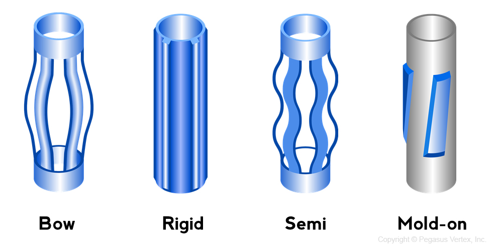
Casing centralizer is a mechanical device secured around the casing at various locations to keep the casing from contacting the wellbore walls. As a result of casing centralization, a continuous annular clearance around the casing allows cement to completely seal the casing to the borehole wall.
Casing centralization is one of the key elements to ensure the quality of a cementing job by preventing mud channeling and poor zonal isolation. Centralizers can also assist in the running of the casing and the prevention of differential sticking.
Centralizer’s usage is extensive! It is estimated that 10 million centralizers are manufactured and used every year globally. Centralizer manufacturers likely want to increase the demand for centralizers. However, operators on the other hand, may wonder: “Should we use that many?”
While centralizers are used extensively, wellbore problems continue to arise due to poor cementing jobs. Centralizer properties and placements directly or indirectly affect the quality of the cementing job.
The challenge that both operators and service companies face is to choose the right type of centralizers and place the right amount at the optimum positions on the casing to achieve a good standoff profile.
There are 4 types of centralizers (Fig. 1): bow-spring, rigid, semi-rigid, and mold-on; each with its own pros and cons.
1. Bow-Spring
Since the bow springs are slightly larger than the wellbore, they can provide complete centralization in vertical or slightly deviated wells. Due to the flexibility of bows, they can pass through narrow hole sections and expand in the targeted locations.
The shape and stiffness of the bows determine the restoring force, which is defined as the resistance force when a bow is compressed by 1/3 of its uncompressed height. The effectiveness of this type of centralizer is heavily dependent on the restoring force.
When the casing is heavy and/or the wellbore is highly deviated, they may not support the casing very well. For example, on a riser tieback casing string, a helically buckled casing could create a side force of 50,000 to 100,000 lbf (222 to 445 kN), well beyond the capabilities of the spring-bow centralizer. A solid centralizer would be able to meet the requirements.
2. Rigid
Rigid centralizers are built out of solid steel bars or cast iron, with a fixed blade height and are sized to fit a specific casing or hole size. This type is rugged and works well even in deviated wellbores, regardless of the side force. They provide a guaranteed standoff and function as bearings during the pipe rotation, but since the centralizers are smaller than the wellbore, they will not provide a good centralization as the bow-spring type centralizers in vertical wells.
3. Semi-Rigid
Semi-rigid centralizers are made of double crested bows, which provide desirable features found in both the bow-spring and the rigid centralizers. The spring characteristic of the bows allows the semi-rigid centralizers to compress in order to get through tight spots and severe doglegs. The double-crested bow provides restoring forces that exceed those standards set forth in the API specifications and therefore exhibits certain features normally associated with rigid centralizers.
4. Mold-On
The mold-on centralizer blades, made of carbon fiber ceramic materials, can be applied directly to the casing surface. The blade length, angle and spacing can be designed to fit specific well applications, especially for the close tolerance annulus. The non-metallic composite can also reduce the friction in extended reach laterals to prevent casing buckling.


