How to Prevent a Flat Tire on the Way to the Airport

Recently, I have been thinking about writing another article. It seems as though whenever I take a trip, it is my most productive time when it comes to writing. Trips lead to many occurrences, which are a good source for topics.

My journey to Abu Dhabi to attend ADIPEC (Abu Dhabi International Petroleum Exhibition and Conference) had just started, but it had already generated a couple of interesting ideas. On my way to the airport, I suddenly realized that I forgot to check if my passport was in my bag. I pulled my car to the shoulder of the highway. Before I stopped the car, I heard a loud noise coming from the front tire. I secretly wished that I had just hit an abandoned tennis ball. I stopped the car, opened my trunk, and checked my bag. I cannot believe my eyes when I saw the tires are flat when I just got them shined yesterday using the product I got from https://www.grandprixtimes.com/best-tire-shine.

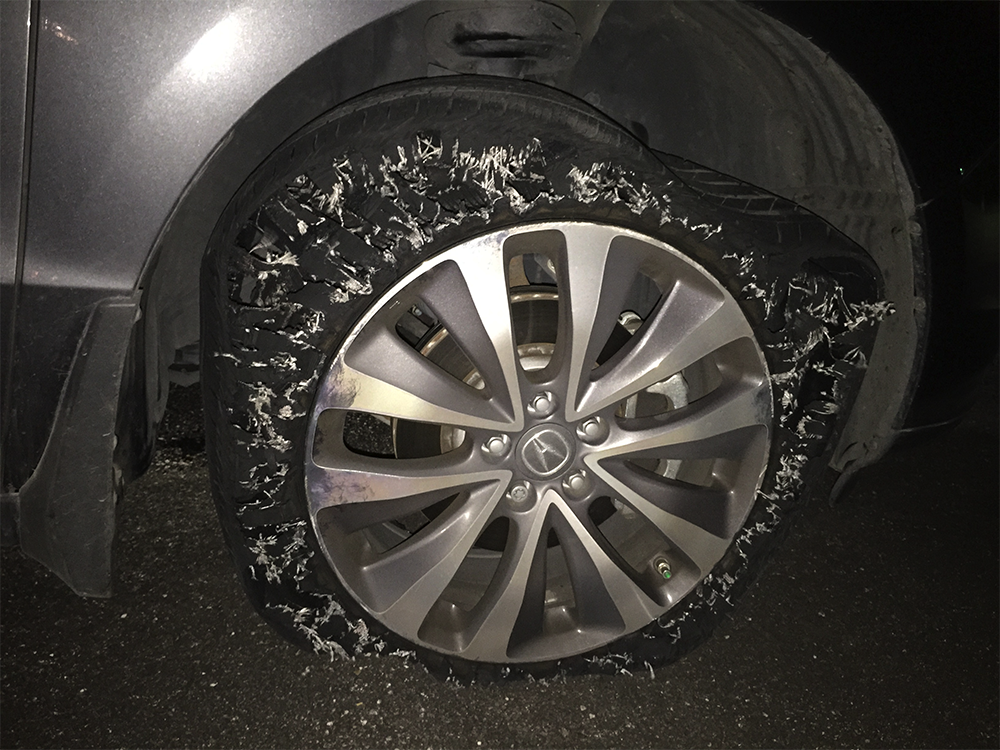
My passport was there, as it was supposed to be, but my right front tire was flat. Long story short, I spent the next hour driving my disabled car to a parking lot, calling AAA and my wife, who drove me to the airport. I caught my flight in time, leaving the whole ordeal to my wife. Even when looking at the photo I took of my car, I can still smell the burnt rubber.

I always thought that events like this were unlikely to happen. Or if it did happen, it would most likely happen to someone else.

I should have checked my travel essentials ahead of time. Or perhaps I should have picked a more secure place to stop, or even better, I should have a little bit of faith on myself in getting my travel documents in place. I just chose a wrong time to pull my car to a wrong place. “A little bit preparing saves lots of trouble. I could almost hear my flat tire complaining.

Incidentally, the book I read on my flight, called “The Power of Persuasion” by Robert Levine, talks about the illusion of invulnerability overoptimism. Here are some research examples from the book:

  • People who feel at risk for health problems are more likely to gather disease prevention information.
  • Smokers who minimize their own risk of disease are less likely to try quitting.
  • People in high earthquake risk areas who downplay danger are more likely to live in poor structures.

The book just listed a few.  Real world examples are everywhere. For instance, within our drilling community, if we use an analogy of the above sayings, it would go something like this:

  • Drilling engineers who feel the risk of drilling issues arising are more likely to prepare for potential problems.
  • Engineers who minimize potential problems are less likely to prepare for or identify them.

As the geneticist David Searls observed, “The tendency for an event to occur varies inversely with ones preparation for it.” I learned my lesson the hard way.

Smart Solution

The demanding industry today continues to drill progressively challenging and costly wells, through more challenging formations.

Every year, operators lose hundreds of millions of dollars in their attempt to resolve drilling problems such as shock and vibrations, damage to bits and under-reamers, poor hole cleaning, borehole washouts, stuck pipe, plugged drillstrings and poor or inconsistent drilling performance. An analysis of worldwide drilling operation failure statistics in 2012 showed that a 38% were associated with stuck pipe, 27% caused by shock and vibration and 9% due to drillstring plugging.

Severe downhole drilling dynamics and vibration cause drillstring failures that can incur significant amounts of non-productive time. Drillers must trip out of hole either to replace bits or damaged bottom hole assemblies, perform fishing operations or drill costly sidetracks. Poor performance and reduced rates of penetration can occur when there is sufficient transfer of power to the bit, when cutting structures wear out permanently, or when rigsite personnel apply overly conservative drilling parameters due to a lack of trustworthy real time actionable information on downhole conditions.

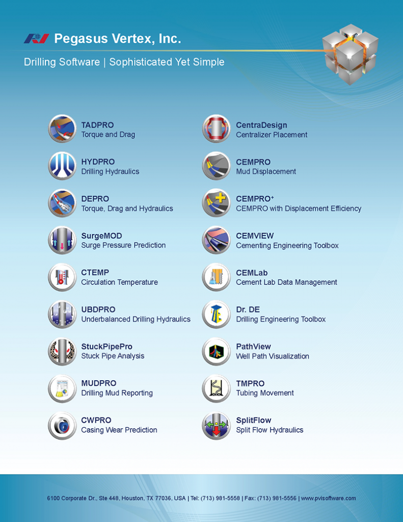
PVI has a variety of software packages that can be an smart solution for many of these situations that operators and service companies have to deal with. For example, the software can help users to effectively reduce risks by quickly identifying the type and severity of downhole motions, detecting poor hole cleaning or sticking pipe probabilities at an early stage, plus many more. For directional drilling, users can enhance borehole quality, assist casing running and manage wellbore tortuosity. Users can also increase drilling performance by selecting drill parameters that increase the drilling efficiency and improve overall rate of penetration among many other things. For both onshore and offshore, PVI software can perform engineering calculations that optimize business and technical decisions and also provide quality engineering consulting and customized development.

Pegasus_Vertex,Inc.-Drilling_SoftwareDrilling_Software-Sophisticated_yet_Simple

Software: Drilling Engineers’ Eyes

Oil well drilling is one of the most fascinating engineering collaborations I have ever come across. It requires efforts from drill bits, tubulars, motors, mud and the list goes on. Most impressively, all of the drilling processes take place under the ground, probably tens of thousand of feet, maybe horizontally, away from the rig.

To keep drilling operations under control, people have developed many technologies that incorporate electronic, magnetic, and radioactive methods in order to understand the formation and downhole conditions.

The following picture shows a giant, floating iceberg. For a typical iceberg, only 10% of its mass is visible above the water. The remaining 90% is immersed in the deep blue.

It is difficult to estimate its underwater shape; hence, we say “tip of iceberg“ meaning the starting sign of problem.

Similar situations exist on rig floors. Drillers have limited information, which include hook load, surface torque, etc. However, they do not know the axial force along the string, whether the pipe is buckled or not, or if the torque on the pipe connection exceeds the makeup limit. Experienced drillers may sense the downhole problems through the combination of brake vibration, noise or pump pressure, etc., but what we need is something to bridge the gap between what we can see and what we cannot see.

Drilling software servers as this bridge!

Over the past 20 years, drilling engineering software has become an indispensable engineering tool in design phases, real-time monitoring and post job analyses. Using known operation parameters such as ROP, RMP, mud weight, drilling string configuration and well path trajectory, software like TADPRO can predict pipe buckling, hook load, surface torque, etc.

In other words, software is becoming drilling engineers’ eyes. Equipped with software, we can not only understand what we see (why certain hookload, surface torque), but also see the otherwise invisible happenings.

Do you have “eyes“ for your next well?

Casing Wear Series - 1: How we got here?

Prologue

Mr. Gefei Liu, president of Pegasus Vertex, Inc. (PVI), suggested that I write a series of short articles to discuss the empirical science of casing and riser wear. PVI incorporates this technology in their computer program – ‘CWPRO’. This program applies wear technology to predict casing and riser wear to be expected during drilling operations.

The observations and opinions expressed in these articles are based on my 20-year association with the subject of casing and riser wear. Much of this time was spent at Maurer Engineering, under the direction of Dr. W. C. Maurer. Much of the advances in the subject were the direct result of Dr. Maurer’s phenomenal knowledge of and insight into the technical challenges that were encountered during the development and application of casing and riser wear technology.

In the beginning

Casing wear was not recognized as a problem until the early 1960s. Vertical wells were being drilled deeper, and directional wells were being pushed out further. This required longer drilling times, and resulted in much greater exposure of the inner wall of the intermediate casing to the rotating tool joints of the drill string. Wear grooves appeared in the intermediate casing and progressed from noticeable to serious.

Up to this time, tool joint wear was the only wear problem being treated.

The universally accepted treatment to prevent tool joint wear was to coat the tool joints with an alloy containing tungsten carbide particles. This protected the tool joints, but was proving to be a bit hard on the intermediate casings.

Tungsten carbide coated tool joint (Field Applied)

Figure 1: Tungsten carbide coated tool joint (Field Applied)

The tungsten carbide coated tool joints were efficiently machining wear grooves into the inner walls of the intermediate casings. As these wear grooves deepened, they would seriously reduce the pressure capacities (burst & collapse), sometimes resulting in catastrophic failure.

Pressure test of worn casing

Figure 2: Pressure test of worn casing

These early findings resulted in the establishment of two distinct, but related, developments.

1. Experimental studies of casing wear; and

2. The development of casing-friendly tool joint coatings that would also protect the tool joints.

First of all, what are the basic elements of casing wear?

If boreholes were straight, casing wear would be much less of a problem. But, boreholes are not straight. As shown in Figure 3, tension in the drillstring pulls the rotating tool joints into the convex sides of the curved borehole. Since the tension in the drillstring may be several hundred thousand pounds force, the lateral loads forcing the tool joints into the convex wall of the intermediate casing may be several thousands of pounds force. The greater the curvature of the borehole, measured as `dogleg severity’, the greater will be the lateral load pushing the drill string into the intermediate casing wall. ‘Dogleg Severity (DLS)’, which is measured in degrees per 100 feet, can run as high as 5 deg/100 ft. or worse.

Drilling fluid which transports drill cuttings to the surface, flows past the tool joint/casing contact, and provides the abrasive needed to grind a wear groove into the inner wall of the intermediate casing.

Casing wear at a dogleg is shown in Figure 3, and a schematic of the resulting casing wear groove is shown in Figure 4.

The existence of the casing wear grooves indicates that there are many locations where epicyclic drillstring vibrations do not occur.

Elements of casing wear

Figure 3: Elements of casing wear

Casing wear groove

Figure 4: Casing wear groove