Return to Square One: A Round Trip without Reaching the Destination

Due to business, I had to make a trip to Saudi Arabia via Paris. It was uneventful from Houston to Newark, where I made connection. I boarded on the flight, the meal was delicious and I took a Benadryl, hoping I could get some sleep on the way to Paris.

While I dreamt, I heard the announcement, “Ladies and gentlemen, as we start our descent…” I woke up and was delighted to imagine that I would be in Paris in a few minutes. Looking at the lights below, I tried to locate the Eiffel Tower. Then, a suspicious feeling arose, it was too soon for us to arrive; we should land in Paris during the day time. Then I heard my neighbor, who had also just woken up, saying, “Why are we landing in Newark?”

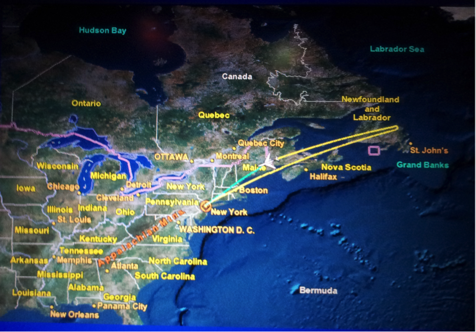
Finally, a flight attendant told us that 3 hours after the airplane took off, as we were just above the Atlantic Ocean, they found some issues with one of the engines. The captain decided to return home. The following is our flight trajectory that night.

Although I am a frequent business traveler, this was my first time experiencing this. I had a meal in the air, took a nap, and then I was back to square one. After all, the airline company must have had its own justification to fly back, and it is better to be safe than sorry.

As a result of this incident, except extra fuel cost, the airline company had to pay for our hotel and meals during delays. Apparently, everyone in this trip lost 6 hours; moreover, it brought about much inconvenience. No one would enjoy these types of surprises. However, the big picture is that the decision on flying back may have saved hundreds of lives. I am certain that airlines are making efforts to ensure flight safety and punctuality.

Drilling operations are like flight missions. There is a destination we want to reach, which we call total depth (TD). We assemble drill pipes, tools and bit. We circulate drilling fluid, control the hook load and weight on bit (WOB) to penetrate. But things could go wrong: pipe may get stuck, circulation lost, or bit dulled. Like this trip, those problems are unpredictable.

What we can do is to engineer the operation more carefully to identify potential problems prior to drilling. With our best effort, we keep the problems under control, and then we can be at ease with the outcome.

Despite the cancelled flight, I had brief but good sleep in a hotel by the airport. The next night, I caught another flight. After dinner, I took another Benadryl. This time, I woke up in Paris!

7 Basic Ideas

In completion of oil and gas wells, cement separates the wellbore, prevents casing failure, and keeps wellbore fluids from contaminating freshwaters. The basic factors engineers and operators must consider for successful cementing jobs are summarized in seven basic ideas:

  1. Condition the Drilling Fluid
  2. Use Centralizers
  3. Move the Pipe
  4. Increase the Displacement Rate
  5. Design Slurries for Proper Temperature
  6. Select and Test Cement Components
  7. Select a Proper Cementing System

1. Condition the Drilling Fluid

The drilling fluid condition is the most important variable in achieving very good displacement during a cementing job. As the workers pull the drill pipe, run the casing, and prepare for cementing operations, the drilling fluid in the wellbore basically remains static and hardens. Pockets of mud commonly exist after a wellbore is drilled and they make displacement difficult. These pockets of gelled fluid must be broken up. Regaining and maintaining good fluid mobility after running the casing is essential.

2. Use Centralizers

Centralizers are effective mud displacement helpers. Centralizers make easier the removal of gelled-mud and allow better cement bond with the wellbore. Centralizers are designed to serve various needs, for instance, they help with well control, provide increased mud-removal benefits, optimize drilling-fluid displacement. When a casing is poorly centralized the cement bypasses drilling fluid by following the path of least resistance. Good pipe standoff helps ensure uniform flow patterns around the casing. Centralizers also change fluid flow patterns and promote better mud displacement and removal.

3. Move the Pipe

Moving the casing before and during cementing breaks up the gelled pockets and it loosens the cuttings trapped in the gelled mud. Pipe movement allows high displacement efficiency at lower pump rates by keeping the drilling fluid flowing.

Movement compensates partially for poorly centralized casing by changing the flow path and allowing the slurries to circulate completely around the pipe. In some instances, some liner hangers and mechanical devices prevent casing movement, which must be considered during the cement displacement design.

4. Increase the Displacement Rate

High-energy flow in the annulus is more effective in ensuring good mud displacement. Turbulent flow around the casing circumference is desirable, but not necessarily essential. The best cementing results are obtained when the spacers and cement are pumped at maximum energy, the spacer is appropriately designed to remove the mud, and a more proficient cement is used.

5. Design Slurries for Proper temperature

Operators can optimize the slurry design if they know the actual temperature the cement will encounter. Bottomhole cementing temperatures affect the slurry thickening time, set time, rheology and the compressive-strength development. Operators tend to overestimate the amount of materials required to keep cement in a flowing for pumping, which can result in unnecessary cost and well-control problems. They can optimize cost and displacement efficiency by designing the job on the basis of actual wellbore circulating temperatures, obtained from a downhole temperature sub recorder.

6. Select and Test Cement components

Operators are encouraged to design cement slurries for specific applications, with good properties to allow placement in a normal period of time. The ideal cement slurries have no measurable free water, provide adequate fluid-loss control, have adequate retarder to ensure proper placement, and maintain a stable density to ensure hydrostatic control.

Before performing the job, they should check the cement reaction and actual location mix water to ensure that the formulation will perform as it is expected. Contaminants in the mix water can produce large variances in thickening time and compressive strength.

Organic materials and dissolved salts in mix water can affect the slurries setting time.

Cement dehydration from the loss of filtrate to permeable formations can cause bridging and increased friction pressure, viscosity, and density. Pump pressures can increase and additives can be used to provide fluid-loss control when is necessary to compensate for dehydration.

7. Select a Proper Cementing System

Operators select cement systems based on job objectives and well requirements.

Cement is basically inflexible. Cementing systems are similar in many ways, but sometimes they vary, for instance, in their capability to provide good zone isolation in changing environments. The cement selection has always been on the basis that higher compressive strengths result in higher cement sheath quality. Research has proven that the ability of cement to provide good zonal isolation is better defined by other mechanical properties. Good isolation does not necessarily require high compressive strength. The real competence test is whether the cement system in place can provide zone isolation for the life of the well.

For all these situations PVI has developed a series of software such as:

CentraDesign - Centralizer Placement Software

CentraDesign - Centralizer Placement Software

MUDPRO - Drilling Mud Reporting Software

MUDPRO - Drilling Mud Reporting Software

StuckPipePro - Stuck Pipe Analysis Software

StuckPipePro - Stuck Pipe Analysis Software

that can help engineers and operators to perform a better quality job and avoid any potential problems that can put at risk the production.
“All that is gold does not glitter” - Drilling Mud

ScienceNewsforKids.org has recently posted an article titled “Mud worth than gold”, which happened to be the “Nose in the News” project for my 3rd grade son. Though this article is a little hard for a 3rd grader to analyze, its title is rather attractive. The article tells the sample mud collected from far below Antarctica’s ice by two scientists and their drilling crew contains valuable information. This might help reveal the secrets of the continent’s ancient climate, thus help on future weather prediction.

Coincidentally, in this September, a report from “marketsandmarkets.com” also has something to say about mud. The report with a long title "Drilling Fluids (Drilling Mud) Market and Completion Fluids Market: by Types (Water-Based Systems, Oil-Based Systems, Synthetic-Based Systems, Other Based Systems), Application Areas (Onshore and Offshore), & Geography - Global trends and forecast to 2018 " defines and segments the global drilling fluids and completion fluids market with analysis and revenue forecast. It predicts that the drilling fluids and completion fluids market will grow from an estimated $10.6 billion in 2013 to $15.2 billion by 2018.

All that is gold does not glitter

Regardless of its meaning and the context, the title of J. R. Tolkien’s poem “All that is gold does not glitter” would certainly apply to drilling mud. According to industry statistics, drilling mud takes approximately 10% to 15% of the total drilling cost. With the needs of more deep sea drilling and ever fast drilling rate, drilling fluids are used on day-to-day basis and plays a vital role in drilling process: controlling formation pressure, sealing permeable formations, stabilizing the wellbore, suspending the drill cuttings, and cooling and lubricating the drilling bit etc.

Drilling fluids are basically categorized into 3 types: water-based mud (WBM), oil-based mud (OBM) and synthetic-based fluid (SBM). When choosing a drilling fluid, factors like well design, cost, technical performance, environmental impact all need to be considered. WBM and OBM are commonly used nowadays. They are complex compositions with various additives such as minerals and chemicals. As the well drilling reaches various depths, it requires different type of drilling fluids to meet the specific drilling condition, where demands the balance between the properties and the additives in the mud. Small problems with mud may lead to severe problems like lost in mud circulation, gas escaping or even blowout.

Among those who work on the drilling rigs, mud engineers are the ones who frequently and closely deal with the drilling mud. Their job is 24/7.  A mud engineer’s duty not only involves in prescribing mud treatments, maintaining the drilling fluids, but also keeping continuous mud reporting every day. To them, time management is more important than ever. Besides powerful computer aids, software like MUDPRO developed by PVI is a great way to enhance the mud engineer’s ability on mud data recording and analyzing, hydraulics calculating, inventory tracking and daily reports/recap generating.

As drilling technology advances, drilling fluids are innovated and designed to be not only cost effective but also environmentally safe. Research on Non-toxic bio degradable drilling fluids with nanotechnology is being conducted and huge investment is being made. This type of fluids not only provides higher transfer efficiency and better thermal conductivity but also removes toxic metals. After all, protecting the environment has enormous impact to our future generations.

Casing Wear Series - 2: The Basics

When it became apparent that casing wear was going to be a matter to be reckoned with, several organizations initiated experimental studies of this phenomenon. Among these were (1) Shell Oil Company, (2) Exxon, (3) Texas A & M, and (4) Drilco. All these operators discovered that experimental casing wear studies were both time consuming and expensive.

All of the casings wear studies involved building a machine that would simulate field conditions as closely as possible in the laboratory. Figure 1 is a symbolic presentation of a casing wear test machine that incorporates all of the parameters needed to simulate casing wear as it would occur under field conditions.

Elements-of-a-casing-wear-test-machine

Figure 1: Elements-of-a-casing-wear-test-machine

As shown in the Figure 1, the rotating tool joint sample is pressed against the inner wall of the casing sample with a constant force. The intersection of the casing and the tool joint is flooded with drilling fluid, which contains sand to simulate the drill cuttings which the mud transports to the surface in field operations.

In addition, the tool joint ( or the casing sample ) should be slowly reciprocated during the wear test to simulate drilling progress. Failure to include this reciprocation results in a significant reduction in the observed casing wear. It is believed that without reciprocation, the casing sample and the tool joint sample will `mate’ to each other, and the drilling fluid will then form a hydrodynamic lubricating layer between the two surfaces. This will greatly reduce the grinding effectiveness of the sand that is transported by the drilling fluid. Non-reciprocating wear tests may result in as little as 10% of the wear observed in tests where reciprocation is employed.

Such a casing wear test machine is pictured in Figure 2. This machine was built by Steve Williamson ( Drilco ) in the early 1980s, and was later purchased by Maurer Engineering for use in the Drilling Engineering Association ( DEA ) projects ( DEA – 8, DEA – 42, and DEA – 137 ). These projects covered the period from 1990 through 2002.

Drilco casing wear test machine

Figure 2: Drilco casing wear test machine

Most of the material presented in these articles was developed as a result of the work done using this machine.