Visual Thinking Equals Creativity

Logical and visual thinking are two different mental groups that affect the way we view things.

The logical thinking involves analysis, advancement from simple to complex, organization of information and continuous reasoning. This group is influenced by hearing and language and a perception of time.

In contrast, visual thinking involves synthesis, an intuitive comprehension of complex systems, coordinated processing of concepts, inductive reasoning from the whole aspect to the small aspects, use of imagination and generation of ideas by combining existing facts in new ways, in other words, creative thinking. This group is influenced by visualization and images and a perception of space.

For the visual thinking group, concepts are rapidly understood when presented with visuals. Once the spatial thinking group has an image of a concept and sees how the information fits with what they already know, their learning ability is permanent. It’s their best learning style. To them, images are their main motivation and it is how they experience success in their own way. With this in mind, here at Pegasus Vertex, Inc. we put a lot of effort into our software development to give our clients a sophisticated visual experience of what goes on below the ground and under the sea. We use diverse visualizations, such as schematics and graphs that provide a live feed of the operations.

Highly Visual | PVI Drilling Software

Visual thinking is one of our main focuses when creating the software.

Why?

Because visuals are a more effective way in understanding the goals of the project, whether it is mud reporting, drilling hydraulics, casing wear prediction, cementing jobs, wellbore trajectory, tubing movement or split flow analysis. With creativity we give our customers the software that fits their needs.

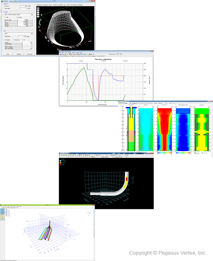
Highly Visual | Drilling Software - Pegasus Vertex, Inc.

Flying Among The Clouds

Louis D. Brandies once said:

“Most of the things worth doing in the world had been declared impossible before they were done. Impossible means that you haven’t found the solution yet.”

A little over 100 years ago there were things that were considered impossible to do and that there was no way they could ever be achieved. For instance, to be able to fly among the clouds, but was it really an impossibility? Time proved that it wasn’t.

Just like flying among the clouds was impossible to do once, there are many things that thanks to the advancement of technology now are possible. For instance, a few decades ago horizontal or extended-reach drilling was considered impossible as well as casing wear prediction. In these environments, casing design is critical to a safe and successful drilling operations and well production, and unexpected casing wear can result in significant costs or even the loss of the well itself. This is the problem that drilling companies want to prevent.

So the question is: Is there any tool or software to calculate and predict casing wear severity? Yes there is! It’s called CWPRO.

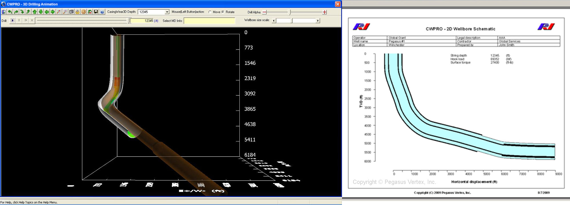
2D wellbore schematic in CWPRO

This casing wear model uses the number of drill string rotations and contact force between the drill pipe and casing to calculate wear. The contact force is calculated using the dogleg severity inside the well. The maximum dogleg severity frequently determines the location and extent of the most severe casing wear. CWPRO helps operators and service companies identify, control and prevent potential problems. In overall the goal of CWPRO is to more accurately quantify casing wear risks and to ensure that the integrity of the casing is maintained during drilling operations.

Like mentioned before, there are many things that were considered an impossibility not too long ago like for instance, flying among the clouds. Likewise, thanks to software like CWPRO, predicting casing wear is no longer impossible; it is a fact.

Casing Wear Series - 1: How we got here?

Prologue

Mr. Gefei Liu, president of Pegasus Vertex, Inc. (PVI), suggested that I write a series of short articles to discuss the empirical science of casing and riser wear. PVI incorporates this technology in their computer program – ‘CWPRO’. This program applies wear technology to predict casing and riser wear to be expected during drilling operations.

The observations and opinions expressed in these articles are based on my 20-year association with the subject of casing and riser wear. Much of this time was spent at Maurer Engineering, under the direction of Dr. W. C. Maurer. Much of the advances in the subject were the direct result of Dr. Maurer’s phenomenal knowledge of and insight into the technical challenges that were encountered during the development and application of casing and riser wear technology.

In the beginning

Casing wear was not recognized as a problem until the early 1960s. Vertical wells were being drilled deeper, and directional wells were being pushed out further. This required longer drilling times, and resulted in much greater exposure of the inner wall of the intermediate casing to the rotating tool joints of the drill string. Wear grooves appeared in the intermediate casing and progressed from noticeable to serious.

Up to this time, tool joint wear was the only wear problem being treated.

The universally accepted treatment to prevent tool joint wear was to coat the tool joints with an alloy containing tungsten carbide particles. This protected the tool joints, but was proving to be a bit hard on the intermediate casings.

Tungsten carbide coated tool joint (Field Applied)

Figure 1: Tungsten carbide coated tool joint (Field Applied)

The tungsten carbide coated tool joints were efficiently machining wear grooves into the inner walls of the intermediate casings. As these wear grooves deepened, they would seriously reduce the pressure capacities (burst & collapse), sometimes resulting in catastrophic failure.

Pressure test of worn casing

Figure 2: Pressure test of worn casing

These early findings resulted in the establishment of two distinct, but related, developments.

1. Experimental studies of casing wear; and

2. The development of casing-friendly tool joint coatings that would also protect the tool joints.

First of all, what are the basic elements of casing wear?

If boreholes were straight, casing wear would be much less of a problem. But, boreholes are not straight. As shown in Figure 3, tension in the drillstring pulls the rotating tool joints into the convex sides of the curved borehole. Since the tension in the drillstring may be several hundred thousand pounds force, the lateral loads forcing the tool joints into the convex wall of the intermediate casing may be several thousands of pounds force. The greater the curvature of the borehole, measured as `dogleg severity’, the greater will be the lateral load pushing the drill string into the intermediate casing wall. ‘Dogleg Severity (DLS)’, which is measured in degrees per 100 feet, can run as high as 5 deg/100 ft. or worse.

Drilling fluid which transports drill cuttings to the surface, flows past the tool joint/casing contact, and provides the abrasive needed to grind a wear groove into the inner wall of the intermediate casing.

Casing wear at a dogleg is shown in Figure 3, and a schematic of the resulting casing wear groove is shown in Figure 4.

The existence of the casing wear grooves indicates that there are many locations where epicyclic drillstring vibrations do not occur.

Elements of casing wear

Figure 3: Elements of casing wear

Casing wear groove

Figure 4: Casing wear groove