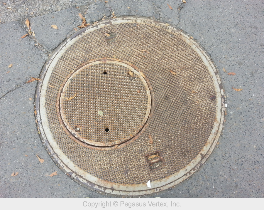
Finding a good picture of an eccentric annulus was challenging until Dennis (Global Sales Manager of PVI) and I walked down a street in downtown Calgary yesterday. I took a picture of this interesting sewerage cover. Dennis immediately guessed what I wanted to do with it, “Picture for your blog article about eccentricity?”
Many drilling engineering textbooks and modeling software assume concentric annulus because it is easy to model the fluid dynamics in it. Unfortunately, the most natural state of pipe in a well is almost always close to one side of the wellbore, if not touching, especially in a deviated well. Casing centralizers keep casing from contacting the wellbore wall. Even with centralizers installed, the casing between centralizers will still deform (sag) and could contact the wellbore.
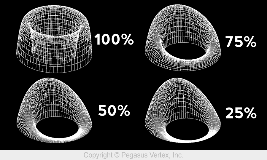
An eccentric annulus has the same cross-section area as the concentric annulus. However, the flow through the eccentric annulus exhibits various forms. The following picture shows the velocity profiles in annuli with various degrees of eccentricity. The percentage represents casing standoff. A standoff of 100% means a perfectly centered pipe while a standoff of 0% represents the situation that the casing is in contact with the wellbore.
The eccentric annulus has many unique characteristics such as less frictional pressure drop than that in concentric annulus. As the standoff gets lower, less energy is required to move the fluid, and mud removal becomes a problem in the narrow side.
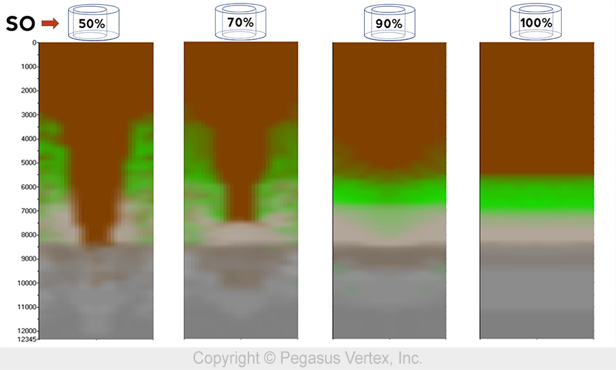
To easily view the numerically simulated results of the fluid mixture in the annulus, we are going to unwrap the annulus into a 2D picture. In this picture, the middle represents the narrow side and the 2 edges represent the wide side.
Picture 3 shows the mud concentration with various standoffs.
A well-centered pipe in a wellbore will lead to a more uniform axial velocity profile and shorter fluid interface length. As standoff approaches 0, the narrow side flow could even be blocked, leaving fluid not displaced.


