A Small World in a Big Airplane


More than 6000 miles away from Houston and 30,000 feet above the ground, I shared a row of seats with a Turkish man who happened to have visited our office 6 years ago. Can anyone tell me what the chance of this occurring is?

After the Abu Dhabi International Petroleum Exhibition and Conference (ADIPEC), I took a flight from Abu Dhabi to Istanbul. During that 4-hour flight, I began sketching some interface designs for our next version of casing wear software. The man seated right next to me was quietly reading a book. After a while, he asked me, “Are you developing a casing design software?” He had obviously seen me write “casing wear” and thought it was “casing design.” I felt pleasantly surprised with his question. “Casing” is a frequently used word in the drilling industry. It is a steel pipe that is assembled and inserted into a wellbore and typically held into place with cement. Outside the petroleum world, it has a very different meaning. Generally, if someone asks me a question about a casing design, not only does that tell me that he is in the industry and familiar with it, but also that he is in the drilling side and familiar with drilling software.

Finding something in common is a good way to break the ice. We began to chat enthusiastically. He was Turkish, but had received an education in the U.S. and was now working with Schlumberger as a drilling engineer. I gave him my business card and he spent a little bit longer than usual looking at it.  He then murmured, “I know you guys…I have been to your office. Don’t you have a software package called MUDPRO?” (MUDPRO is our mud reporting software). Dale Carnegie once said, “A person’s name is to that person the sweetest sound in any language.” This same rule applies to names of family members, friends or even one’s own software products! I felt touched. He explained to me that he has a friend, who owned a mud company. The owner of the mud company visited our office in Houston 6 years ago and he happened to be with him during this trip. It must have been the logo on my business card that reminded him of the meeting, which I had not been a part of.

“What a small world!”  We exchanged mutual feelings.

Chatting with him not only made the flight shorter, but also memorable.

I would never have anticipated this meeting, but an unnoticed event years ago led to this very occasion. “Don’t judge each day by the harvest you reap, but by the seeds that you plant,” said Robert Louis Stevenson, a Scottish novelist from the 19th Century.

Though we are not guaranteed to have harvests every day, we can plant seeds as often as we wish, even every day. The world gets smaller as we plant more seeds daily.

How to Prevent a Flat Tire on the Way to the Airport

Recently, I have been thinking about writing another article. It seems as though whenever I take a trip, it is my most productive time when it comes to writing. Trips lead to many occurrences, which are a good source for topics.

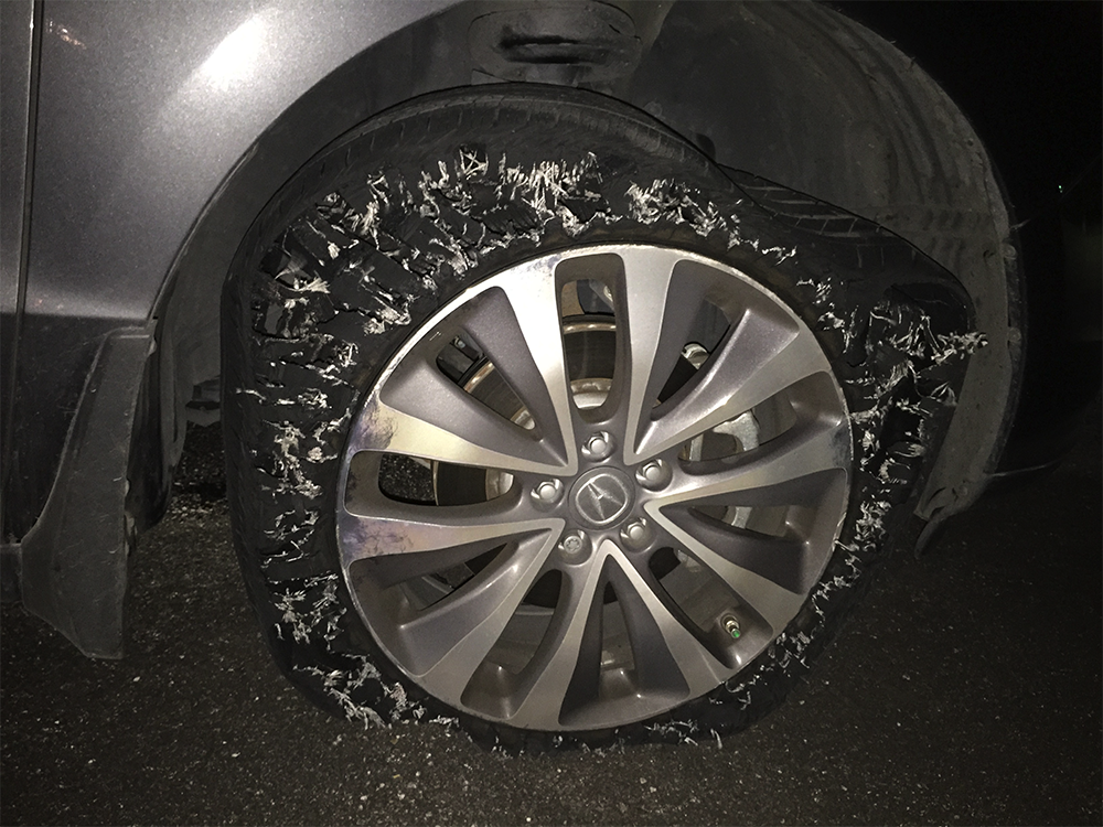
My journey to Abu Dhabi to attend ADIPEC (Abu Dhabi International Petroleum Exhibition and Conference) had just started, but it had already generated a couple of interesting ideas. On my way to the airport, I suddenly realized that I forgot to check if my passport was in my bag. I pulled my car to the shoulder of the highway. Before I stopped the car, I heard a loud noise coming from the front tire. I secretly wished that I had just hit an abandoned tennis ball. I stopped the car, opened my trunk, and checked my bag. I cannot believe my eyes when I saw the tires are flat when I just got them shined yesterday using the product I got from https://www.grandprixtimes.com/best-tire-shine.

My passport was there, as it was supposed to be, but my right front tire was flat. Long story short, I spent the next hour driving my disabled car to a parking lot, calling AAA and my wife, who drove me to the airport. I caught my flight in time, leaving the whole ordeal to my wife. Even when looking at the photo I took of my car, I can still smell the burnt rubber.

I always thought that events like this were unlikely to happen. Or if it did happen, it would most likely happen to someone else.

I should have checked my travel essentials ahead of time. Or perhaps I should have picked a more secure place to stop, or even better, I should have a little bit of faith on myself in getting my travel documents in place. I just chose a wrong time to pull my car to a wrong place. “A little bit preparing saves lots of trouble. I could almost hear my flat tire complaining.

Incidentally, the book I read on my flight, called “The Power of Persuasion” by Robert Levine, talks about the illusion of invulnerability overoptimism. Here are some research examples from the book:

  • People who feel at risk for health problems are more likely to gather disease prevention information.
  • Smokers who minimize their own risk of disease are less likely to try quitting.
  • People in high earthquake risk areas who downplay danger are more likely to live in poor structures.

The book just listed a few.  Real world examples are everywhere. For instance, within our drilling community, if we use an analogy of the above sayings, it would go something like this:

  • Drilling engineers who feel the risk of drilling issues arising are more likely to prepare for potential problems.
  • Engineers who minimize potential problems are less likely to prepare for or identify them.

As the geneticist David Searls observed, “The tendency for an event to occur varies inversely with ones preparation for it.” I learned my lesson the hard way.

PVI does not eat lunch alone

As new studies shed light on organizations and communication practices within companies, we learn to carry-on a variety of exercises to improve what many would consider part of the work-socialization process. As a newcomer to Pegasus Vertex, I have appreciated the consistency that has been put in valuing interactions between co-workers, creating not only a more dynamic, but a more inclusive work environment as well. Last week, the PVI team embarked on what we like to call a “Lunch and Share” meeting. The name is pretty straight forward, here’s a hint: lunch and sharing were involved! But in all seriousness, the reason behind Lunch and Share was to get everyone out of their shells, to interact, or like our company president Gefei Liu would say, “It is a way to enhance ‘a meeting of the minds’ where we can establish a team mindset, a tandem. Sharing is gaining, just like giving is gaining, and we extend each other’s experiences by doing so.”

The results transcended our expectations; employees were more than willing to vocalize their thoughts and listen to what their peers had to say. We started off with a simple assignment to employees, which consisted of sharing what each person did during the summer. It is impressive how such a simple task of sharing one’s experiences can enhance group cohesiveness. Even in industries where one might not consider such activities necessary, one must reconsider in order to enrich interactions between co-workers.

Following this Lunch and Share session, we conducted a brief anonymous online survey to find out how PVI employees felt about Lunch and Share meetings. 100% of respondents communicated enjoying these meetings because they had the opportunity to share with their co-workers. Also, 96% of respondents enjoyed Lunch and Share and 25% believe we should have them more frequently. We were also very open to criticism, where 25% of respondents indicated adequate time limits for each presentation. We took this feedback and plan to tweak a few things in order to meet our employees’ expectations. It is through these types of open relationships with employees that we try to improve socialization skills in the work environment. It was a very effective way of efficiently communicating with one another, sharing our views, and learning with and about each other. This is indeed one of the greatest virtues of PVI, we work hard and give 100%, but we do not forget to engage in the basic needs of human interaction, especially among each other. The survey results reflect just that, and we believe that they have made an incredible difference.

Return to Square One: A Round Trip without Reaching the Destination

Due to business, I had to make a trip to Saudi Arabia via Paris. It was uneventful from Houston to Newark, where I made connection. I boarded on the flight, the meal was delicious and I took a Benadryl, hoping I could get some sleep on the way to Paris.

While I dreamt, I heard the announcement, “Ladies and gentlemen, as we start our descent…” I woke up and was delighted to imagine that I would be in Paris in a few minutes. Looking at the lights below, I tried to locate the Eiffel Tower. Then, a suspicious feeling arose, it was too soon for us to arrive; we should land in Paris during the day time. Then I heard my neighbor, who had also just woken up, saying, “Why are we landing in Newark?”

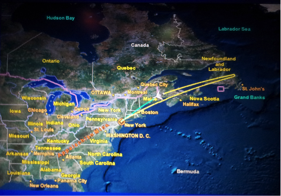
Finally, a flight attendant told us that 3 hours after the airplane took off, as we were just above the Atlantic Ocean, they found some issues with one of the engines. The captain decided to return home. The following is our flight trajectory that night.

Although I am a frequent business traveler, this was my first time experiencing this. I had a meal in the air, took a nap, and then I was back to square one. After all, the airline company must have had its own justification to fly back, and it is better to be safe than sorry.

As a result of this incident, except extra fuel cost, the airline company had to pay for our hotel and meals during delays. Apparently, everyone in this trip lost 6 hours; moreover, it brought about much inconvenience. No one would enjoy these types of surprises. However, the big picture is that the decision on flying back may have saved hundreds of lives. I am certain that airlines are making efforts to ensure flight safety and punctuality.

Drilling operations are like flight missions. There is a destination we want to reach, which we call total depth (TD). We assemble drill pipes, tools and bit. We circulate drilling fluid, control the hook load and weight on bit (WOB) to penetrate. But things could go wrong: pipe may get stuck, circulation lost, or bit dulled. Like this trip, those problems are unpredictable.

What we can do is to engineer the operation more carefully to identify potential problems prior to drilling. With our best effort, we keep the problems under control, and then we can be at ease with the outcome.

Despite the cancelled flight, I had brief but good sleep in a hotel by the airport. The next night, I caught another flight. After dinner, I took another Benadryl. This time, I woke up in Paris!

How to Optimize Bridging Blend to Seal the Formation Surface (Part III)

The best way to optimize parameters is to use software like PVI’s BridgePRO, the bridging agent size selection software, to formulate the PSD to most effectively seal the reservoir formation. The software optimization simulation iterates up to 4,600,000 calculations to find the best possible solution according to the target line position, blend volume % of each product, coefficient of determination and the deviation results. The two optimization parameters to determine the best blend formulation are coefficient of determination and deviations.

  1. Coefficient of Determination, R2
    Coefficient of determination [1] is a measure used in statistical model analysis to assess how well a model explains and predicts future outcomes. It is indicative of the level of explained variability in the model. The coefficient, also commonly known as R-square, is used as a guideline to measure the accuracy of the model.
    BridgePRO uses the coefficient of determination to test the goodness of fit of the blend line to the target line. It is expressed as a value between zero and one. A value of one indicates a perfect fit. A value of zero, on the other hand, would indicate that the blend line fails to accurately model the target line.
  2. Deviations
    BridgePRO optimization simulation takes into account the deviation of five points on the formation characteristics target line with the corresponding points on the blend formulation line. The points considered on the cumulative volume % vs. diameter target and blend lines are D10, D25, D50, D75 and D90. Ideally, the best blend line should have the smallest and positive deviations. BridgePRO takes into account both coefficient of determination and the deviations to determine the best blend line slightly on the right side of the target line.

In conclusions, non-damaging RDF design starts with selecting bridging agents with an ideal size distribution to effectively seal the formation surface.

Abrams’ 1/3 rule defines the effectiveness of a bridging material to initial mud solids invasion. However, it does not give optimum size or address the best packing sequence of particle size for minimizing fluid invasion and optimizing sealing.

The ideal packing theory defines the full particle range required to seal all pores, even those created by the bridging agents.

BridgePRO simulation finds the best possible blend formulation according to the target line position, blend volume % of each product, coefficient of determination and the deviation results.

References

  1. Pavel E. Guarisma, Least squares regression, North Carolina State University, http://herkimershideaway.org/apstatistics/ymmsum99/ymm333.htm

How to Optimize Bridging Blend to Seal the Formation Surface (Part II)

There are following methods to optimize blending formulation.

  1. Graphical Approach of IPT
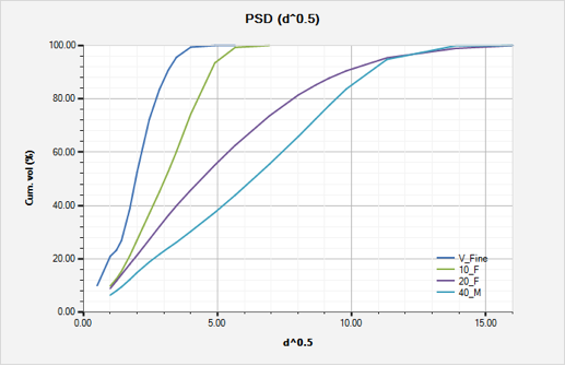
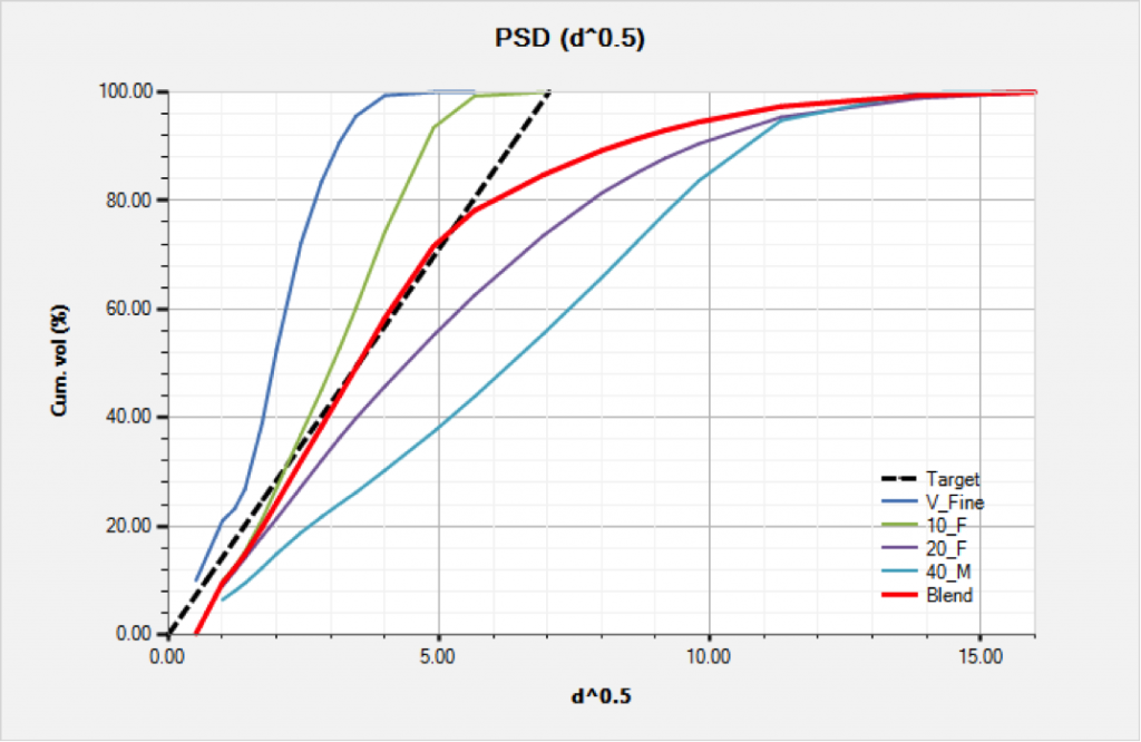
    Dick [1] took a graphical approach to determine the optimum particle-size distribution of bridging material for the given formation characteristics. A wide range of commercially available bridging agents is plotted on the same graph utilizing the D1/2 rule as shown in Fig. 3. Although there is no single bridging agent that exactly matches the optimum target line, a more ideal formulation can be achieved by blending various sized-bridging agents to seal the targeted formation as shown in Fig. 4.

    Fig 3. Commercially available products for bridging permeable formations

    Fig 3. Commercially available products for bridging permeable formations

    Fig 4. The blend PSD line and the target line

    Fig 4. The blend PSD line and the target line

  2. Optimum Target Line
    An optimum target line based on formation information must be plotted before the optimum bridging agent blend can be determined. The design process normally starts with the “worst-case” possibility based on the largest dominant pore size or fracture width. The preferred method is to use pore sizing data from thin section analyses. However, if pore sizing data is not available then the formation permeability information can be used to determine the optimum target line.
    Zhang [2] proposed methods for determining the optimum target line. His rule is:

    1. Select the largest represented pore size from thin section analyses. This is the D90 point on the target line or 90% of cumulative volume shown in Fig. 2.  D90 means 90% of the particles are smaller than size X.  A straight line is then plotted by connecting the origin of Cartesian coordinate to the D90 point.
    2. If the pore size data is not available then the known permeability of the formation can also be used.
      1. If the maximum permeability is available then the maximum pore size D90 point can be estimated by taking the square root of the maximum permeability (in mDarcy).
      2. If the average permeability is known then the medium pore size D50 can be estimated by taking the square root of the average permeability (in mDarcy). The target line and the largest pore size D90 can be extrapolated by connecting the origin of Cartesian coordinate to the D50 point.
  3. Blend Line
    Blending the proper ratio of bridging materials can help to obtain a more ideal formulation for sealing a given reservoir formation. The particle size distribution of the blend line should have a slope close to that of the optimum target line. The blend line is preferably slightly on the right side of the optimum target line. Experience [3] shows that this ideal formulation generally composed of three grades of bridging agents with different particle size as shown in Fig. 4. Calcium carbonate with a different particle size is commonly being used as bridging agents.
    It has been found that 2-3% by volume (20-30 lb/bbl or 60-90 kg/m3) of a proper blend of bridging agents can provide an optimum seal on the face of permeable zones in clean fluids. In heavier weighted fluids, such as those containing barite, guidelines are more flexible with emphasis on larger diameter particles, recommend 3-5% by volume of properly sized solids. Yan [5] recommended the size of the coarse particles should be 4-5 times larger than the very fine particles in order to achieve the highest packing efficiency.

References

  1. SPE 58793, Optimizing the Selection of Bridging Particles for Reservoir Drilling Fluids M.A. Dick, T.J. Heinz and C.F. Svoboda, M-I L.L.C., and M. Aston, BP Amoco
  2. ZHANG Jin-bo,YAN Jie-nian. New theory and method for optimizing the particle size distribution of bridging agents in drilling fluids[J]. Acta Petrolei Sinica, 2004, 25(6): 88-91,95.
  3. SPE 104131,  Design of Drill-in Fluids by Optimizing Selection of Bridging Particles, Yan Jienian, SPE, and Feng Wenqiang, China U. of Petroleum, Beijing

How to Optimize Bridging Blend to Seal the Formation Surface (Part I)

Protecting the pay zone from damage is critical to realize the full potential of any well. Reservoir drill-in fluids (RDF) are designed to prevent formation damage due to fluid invasion and solids plugging. A poorly designed RDF may react with the formation fluid creating blockage or restriction for the natural flow of the reservoir. A large range of undesired solid particles from drill solids, fluid chemicals and clay viscosifiers may end up plugging the reservoir pores. The technique for designing a non-damaging RDF is to start with selecting bridging agents with an ideal size distribution to effectively seal the formation surface.

We are going to list a couple of theories behind bridging agent size selection.

  1. Abrams’ rule
    Abrams [1] proposed a rule for formulating minimally invading, non-damaging drill-in fluids. This rule states that the mean particle size of the bridging agent should be equal to or slightly greater than 1/3 the medium pore size of the targeted formation. For example, the rule predicted that those 50μm bridging particles should be effective at sealing pores up to or around 150μm in diameter. Abrams also suggested that the concentration of the bridging solids used should be at least 5% by volume (50 lb/bbl or 150 kg/m3) of the solids in the fluid.
    However, Abrams only addresses the particle size that initiates a bridge. His rule does not give the optimum size or address the best packing sequence of a particle size for minimizing fluid invasion and optimizing sealing. The fluid design using these guidelines tends to use a wide range of particles in an attempt to provide a wide range of bridging capabilities.
  2. Ideal Packing Theory (IPT)
    Ideal Packing Theory can be defined as a full range of particle size distribution required to effectively seal all voids, including those created by bridging agents.
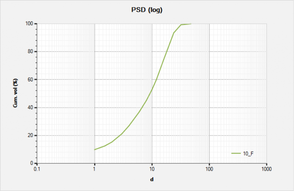
    Fig. 1 shows a typical particle-size distribution for a solid bridging material. Generally, the cumulative volume curve forms an S-shape when plotted on semi-log coordinates. Any commercially available particle-size analysis devices can generate these S-shape plots.

    Fig1. PSD of a Commercial Bridging Product

    Fig 1. PSD of a Commercial Bridging Product

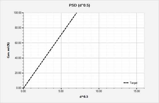
    Kaeuffer [2] employed theories for particles by Furnas and Fuller-Bollomey to generate a simple Ideal Packing Theory also known as the D½ rule. This rule states that ideal packing occurs when the percent of cumulative volume vs. the D½ forms a straight-line relationship as shown in Fig. 2, where D½ is square root of the particle diameter. These subsequent layering of bridging agents results in a tighter and less invading filter cake.

    Fig 2. Ideal Packing

    Fig 2. Ideal Packing

References:

  1. Abrams, A.: “Mud Design to Minimize Rock Impairment Due to Particle Invasion,” JPT (May 1977) 586.
  2. Kaeuffer M.: Determination de L'Optimum deRemplissage Granulometrique et Quelques proprieties S’y Rattachant. Presented at Congres International de I’A.F.T.P.v., Rouen, Oct. 1973

Issues and Their Consequences

Production engineers used to believe that temperature was not a big issue when drilling a well and they could assume worst-case scenarios, such as constant bottomhole flowing temperature throughout the production tubing. However, deepwater drilling and high pressure/high temperature wells have had a change of perspective in engineers and the effects of trapped annular pressure and circulating temperature have become an issue for well completions.

Cathodic Protection System is a proven and reliable method of achieving corrosion control in industrial metals. Corrosion happens to be a progressively destructive process, which is initially challenging to identify until it has advanced. In most cases, corrosion is often identified when it is too late.

The effect of temperature on cementing has long been recognized and it is known that the correct determination of retarder can be critical. Usually, intermediate-string cementing is focused on achieving a great cement job and drilling ahead and not so much on issues of temperature and pressure. One of the reasons is because of the extensive use of water-based drilling fluids. Because water density is not particularly sensitive to temperature and pressure, the surface-measured mud weight does not vary much in conventional wells. However, oil-based and synthetic oil-based muds are very sensitive to temperature and pressure.

In the present, deepwater wells are encountering a lot of extreme temperature and pressure conditions. Maintaining the right pressure and predicting circulating temperature has become more critical due to weak formations and the presence of risers and choke/kill/boost lines.

Pegasus Vertex, Inc. has created CTEMP; a technological software that predicts the well bore circulating temperature for drilling/circulating operations.

CTEMP - Circulation Temperature Software

CTEMP addresses the transient heat transfer between the wellbore and the sea water/rock formation. CTEMP’s interactive on-screen graphic results provide operation guidelines for expensive HPHT drilling operations.

For a successful wellbore stability or well control it is very important that we understand and are aware of all these issues and their consequences.

Eccentric Annulus in a Cement Job

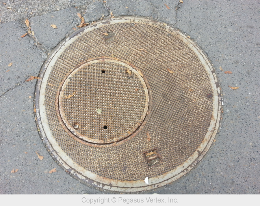
Finding a good picture of an eccentric annulus was challenging until Dennis (Global Sales Manager of PVI) and I walked down a street in downtown Calgary yesterday. I took a picture of this interesting sewerage cover. Dennis immediately guessed what I wanted to do with it, “Picture for your blog article about eccentricity?”

Eccentric Annulus

Picture 1: Eccentric Annulus

Many drilling engineering textbooks and modeling software assume concentric annulus because it is easy to model the fluid dynamics in it. Unfortunately, the most natural state of pipe in a well is almost always close to one side of the wellbore, if not touching, especially in a deviated well. Casing centralizers keep casing from contacting the wellbore wall. Even with centralizers installed, the casing between centralizers will still deform (sag) and could contact the wellbore.

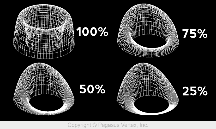
An eccentric annulus has the same cross-section area as the concentric annulus. However, the flow through the eccentric annulus exhibits various forms. The following picture shows the velocity profiles in annuli with various degrees of eccentricity. The percentage represents casing standoff. A standoff of 100% means a perfectly centered pipe while a standoff of 0% represents the situation that the casing is in contact with the wellbore.

Velocity Profiles

Picture 2: Velocity Profiles

The eccentric annulus has many unique characteristics such as less frictional pressure drop than that in concentric annulus. As the standoff gets lower, less energy is required to move the fluid, and mud removal becomes a problem in the narrow side.

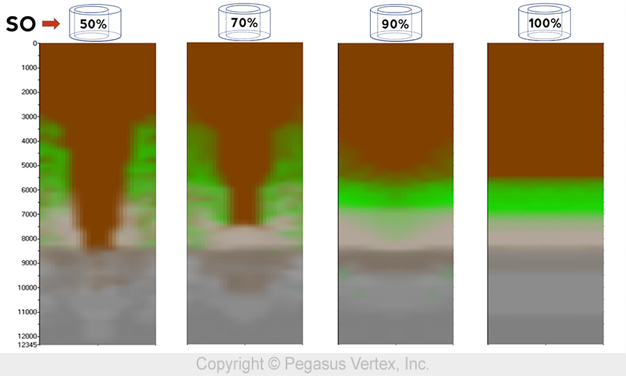
To easily view the numerically simulated results of the fluid mixture in the annulus, we are going to unwrap the annulus into a 2D picture. In this picture, the middle represents the narrow side and the 2 edges represent the wide side.

Picture 3 shows the mud concentration with various standoffs.

Mud Concentration for Various Standoff

Picture 3: Mud Concentration for Various Standoff

A well-centered pipe in a wellbore will lead to a more uniform axial velocity profile and shorter fluid interface length. As standoff approaches 0, the narrow side flow could even be blocked, leaving fluid not displaced.

From the Designing

Cementing operations represent one of the more crucial aspects regarding well integrity. Despite the vast amount of research and the large number of operations throughout the years, well integrity problems, during and after cementing jobs, is something the industry still faces. These problems have been experienced by the petroleum industry globally and can occur at any moment of the well’s life cycle. Well integrity issues have been categorized according to the moment at which they happen:

  1. During the cement displacement in the wellbore.
  2. After the cement placement.
  3. After the cement has been cured.

The first category may result in very serious well-control problems, including blowouts. During the period between 1992 and 2006, the leading cause for blowouts was cementing. These problems usually occur because of improper design of the cementing operations due to hydrostatic pressure of the cement slurries, failure when mixing the slurries to obtain the desire density, and lost circulation during the cement displacement.

The second category is normally associated with the loss of hydrostatic pressure of the cement slurries during the initial hydration period. This also can cause we-control problems, pressure build up in the annulus between the casing strings and zonal isolation problems eventually and the remedial solutions for this are normally expensive and difficult.

The last category refers to long-term problems normally caused by poor cementing jobs. Defective drilling mud removal during the cement slurry displacement in the annulus, insufficient cement height that may lead to casing leakage and corrosion problems are some of the factors that can contribute to long-term well integrity failures and the cost to fix these problems are highly expensive.

PVI has taken into consideration these types of problems and has created two great software for these situations: CEMLab and CEMPRO+.

CEMLab - Cement Lab Data Management Software

CEMLab - Cement Lab Data Management Software

This integrated database management application formulates slurries and calculates lab amounts for all ingredients such as cement, dry and liquid additives, salts and water. It also generates weigh-up sheets, stores API test results and generates lab reports. CEMLab allows quick access to all slurry formulations and testing statuses from anywhere, anytime.

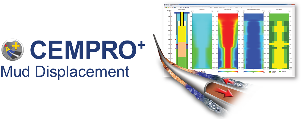
CEMPRO+ : Mud Displacement Software

CEMPRO+ : Mud Displacement Software

This mud displacement program has the capability of displacement efficiency modeling. Designed for land, offshore, conventional and/or foamed operations, CEMPRO+ accounts for many factors that can affect the efficiency of a displacement job including fluid properties, pumping rates, casing standoff and complex wellbore geometry. CEMPRO+ is the must have software for cementing operations.

Before designing your next well, keep these two models in mind to help you achieve, from the designing of the slurries to the mud displacement, a successful cementing operation.