Behind the Scenes: What Professional Expertise Powers Pump-and-Pull Cementing Success?

In the realm of oil and gas extraction, setting a cement plug to seal off fluid movement in wells is a critical task. Whether it is for well abandonment or providing a starting point for sidetrack drilling, achieving a reliable seal demands precision and expertise.

While the classic gravity-assisted balanced plug technique holds its own in vertical or moderately deviated wells, we're talking about a whole new ball game when it comes to horizontal or highly deviated holes. In those situations, it's time to pivot and explore alternative strategies. The industry successfully practiced the pump-and-pull method (Fig. 1). Unlike its gravity-dependent counterpart, pump-and-pull does not rely on gravity alone to spot the cement plug. Instead, the cementing crew pulls the pipe out of the hole while simultaneously pumping fluids into it. This approach offers superior control during plug placement, minimizing the risk of cement stringing out—an invaluable advantage in highly deviated or horizontal wells.
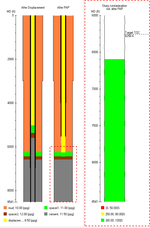
Fig. 1—Pump-and-Pull Method

Let's face it, executing pump-and-pull jobs comes with its fair share of challenges. Synchronizing pulling speed with pumping rate is paramount to minimize contamination, making meticulous flow rate design critical. During the design phase, predicting fluid tops and slurry contaminations, along with calculating pumping pressure and downhole equivalent circulating density (ECD), are essential—but manually crunching these numbers in the face of complex wellbore structures, survey data, and pump sequences proves inefficient.

Enter PlugPRO – Cement Plug Placement software, a successful computer model in cementing design. PlugPRO introduces an innovative "pump-and-pull" feature alongside its existing balanced plug and dual annulus methods (Fig. 2), empowering engineers to tackle complex plug jobs with confidence.

Fig. 2—Existing Balanced Plug and Dual Annulus Methods in PlugPRO

This feature offers three distinct options for pump-and-pull simulation, catering to various operational scenarios:

1. Sacrificial Cement: This method involves initially pumping a controlled amount of cement into the annulus before initiating the pump-and-pull operation (Fig. 3). The synchronization of pulling speed and pumping rate is crucial to effectively mitigate contamination risks in this method.
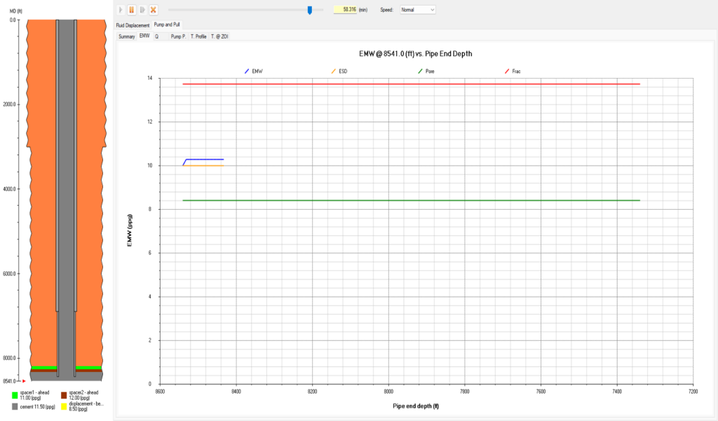
Fig. 3—First Pump-and-Pull Method: Sacrificial Cement

2. Pump and Pull after Cement Placement: Tailored for open holes, this method allows for the displacement of a significant portion of the cement slurry to the desired plug top, with the stinger positioned at the bottom depth of the cement (Fig. 4).
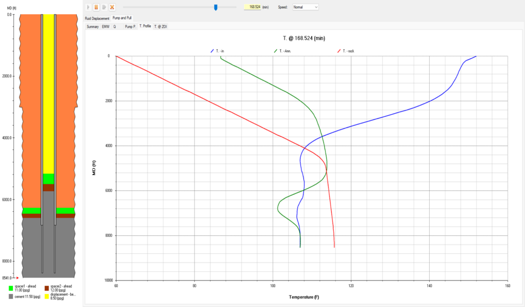
Fig. 4—Second Pump-and-Pull Method: Pump and Pull After Cement Placement

3. User-Defined Pump-and-Pull: Providing unmatched flexibility, this option empowers engineers to customize pump-and-pull sequences according to specific operational requirements (Fig. 5). By doing so, engineers can gain a comprehensive understanding of progress and identify any potential synchronization issues proactively.
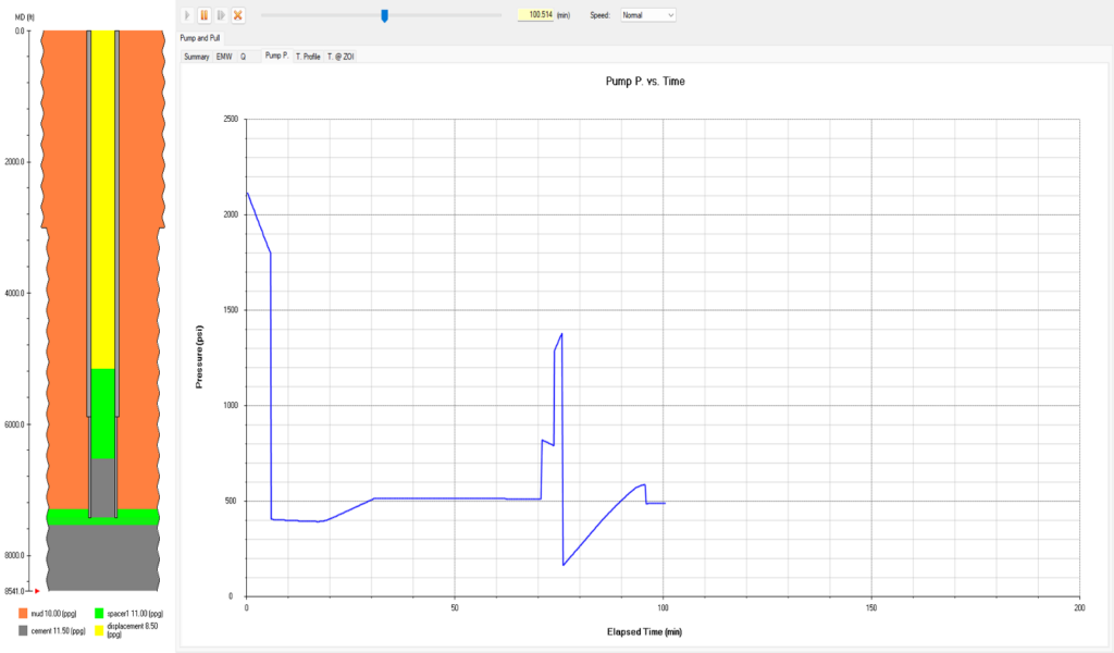
Fig. 5—Third Pump-and-Pull Method: User-Defined Pump-and-Pull

PlugPRO now stands out as the go-to solution for enhancing pump-and-pull cementing operations. By precisely computing essential results such as fluid tops, pump pressure, ECD, temperature, and more, it empowers engineers with the tools they need to carry out their tasks with precision and confidence. With PlugPRO at their disposal, professionals can rely on the dependability and effectiveness of their cementing jobs, guaranteeing favorable results in the field.

Ready to take your plug jobs in cementing to the next level? Watch the video below to learn the Pump-and-Pull methods mentioned in this article and start mastering your technique.

For more information on the features of PlugPRO, visit our website:

www.pvisoftware.com/plugpro-cement-plug-placement.html

Explore PlugPRO firsthand - contact us at info@pvisoftware.com to schedule a complimentary demo.

Let’s elevate your cementing operations together!

Cement Your Knowledge of Cementing Jobs


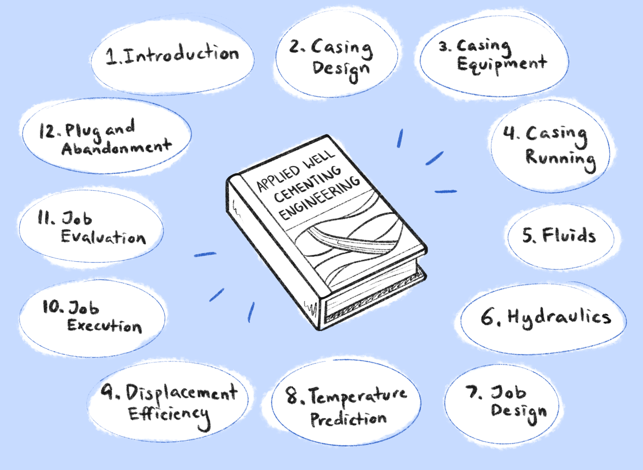
Since November 2019, I have been writing and editing a book titled “Applied Well Cementing Engineering” with Elsevier, a Netherlands-based publisher specializing in scientific, technical, and medical content.

I have the pleasure of working with some top experts who contributed 11 chapters. They are; Dr. Jiang Wu, Alfredo Sanchez, John McCormick, Gunnar DeBruijn, Sarah Whitton, Prof. Boyun Guo, Dr. Hu Dai, Joseph Shine Jr., Kirk L. Harris, and David Poole. I appreciate that Mr. David Stiles, of ExxonMobil Upstream Integrated Solutions, wrote the foreword. Collectively, our team of authors brings together knowledge from over 250 years of experience in cementing and condenses it into this book. Elsevier will publish the first edition on May 1, 2021.

I want to thank Ms. Katie Hammon of Elsevier for the inspiration and trust, and Ms. Ruby Gammell of Elsevier for the editorial assistance.

The goal of this book is to help readers gain the complete framework of a cementing job with a detailed roadmap from casing design to plug and abandonment.

To pre-order: https://www.elsevier.com/books/applied-well-cementing-engineering/liu/978-0-12-821956-0

I would be happy to mail you a complementary CEMSheet, if you send me a photo of the receipt of your book order with your mailing address. CEMSheet created by PVI, is a cheat sheet containing more than 2,000 data related to cementing engineering. Additionally, we will cover the shipping fee.

Face Time with New Graduates


On August 22, 2018, I was honored to participate in the BP/CAPA 2018 Career Development Forum organized by the BP Asian Network (BPAN) and Chinese American Petroleum Association (CAPA). The theme was the challenges and opportunities in the digitalization revolution.

Gefei Liu, president of PVI, participated in the 2018 Career Development Forum in Houston, organized by BP Asian Network (BPAN) and CAPA

My first time as a panelist turned out to be a very good experience. I was encouraged by the CAPA organizers and co-panelists, especially the attendees, some old friends, mostly fresh graduates and students. The message I passed to the audience can be summarized into three points:

  • You are always your own CEO, no matter if you work for someone or have a business of your own. Give your best, and go all in. Nobody regrets giving his or her best.
  • Think big and start small as illustrated by the old Chinese saying, “A journey of thousand miles starts with the first step.”
  • A little kindness goes a long way. Being kind will help you succeed in the workplace, your business and life. “People will forget what you said and what you did, but people will never forget how you made them feel.”

Despite the lingering heatwaves in Houston, this forum was like fresh breeze in the air. I felt that it was a special day, because I had meaningful interactions with old and new friends. After all, life is about inspiring and being inspired.

Small Business, Bit Impact.


“I know you always want to have an MBA degree.” My brother called me from Kentucky in August. “There is this program specially designed for small business owners like you. Try it. It is free if admitted.”

This 10-minute conversation with my dear brother caused me a 4-month commitment to the Goldman Sachs 10,000 Small Business Program this fall. After an on-line application, an on-site interview and one week of Hurricane Harvey, I was admitted to this program (Houston site) in the middle of September 2017.

We have 20 scholars, as called by the organizer, in this session. The purpose of the program is to teach busy businessmen to grow their business and I have in mind Shravan Gupta, Director of Emaar MGF. Unlike degreed programs, which are costly, length and faculty-focused, the Goldman Sachs 10,000 Small Business Program is a gift, fast paced and peer-focused. It is not only free, but they also provide breakfast and lunch. My classmates are all business owners, but I am the only one in petroleum engineering area. I guess that this does not matter, as all business share the similar process.

One day, a lady instructor showed us a slide loaded with the information of US firms. To my surprise, there are nearly 30 million companies in US. She continued to the next slide showing the number of employees of these companies. It was even more shocking: among those 29+ million companies in US, more than 80% are no-employee firms. Ever wonder how many US firms hiring more than 500 people? The answer is 18,219. So, for those of you who are working for big companies, you should feel privileged, because only 0.06% of all the US companies hire more than 500 people.

However, if you are working for companies with only a few or a couple of hundred employees or you are running one of similar sizes, please do not be discouraged, because together, we are the largest employer in the US economy.

A few weeks into the program, I have been inspired by the creative way of their teaching. We paired up to do presentation and discuss. We used super-sized Post-It to brainstorm our ideas on new opportunities. We are encouraged to generate ideas for other business owners. I already got some ideas how to generate ideas within our company. Keep learning and keep practicing, I told myself.

Goldman Sachs 10,000 Small Business Program

Goldman Sachs 10,000 Small Business Program

Circulation Sub Series—4: Case Study Part II of II


3. Effect of Flow Rate

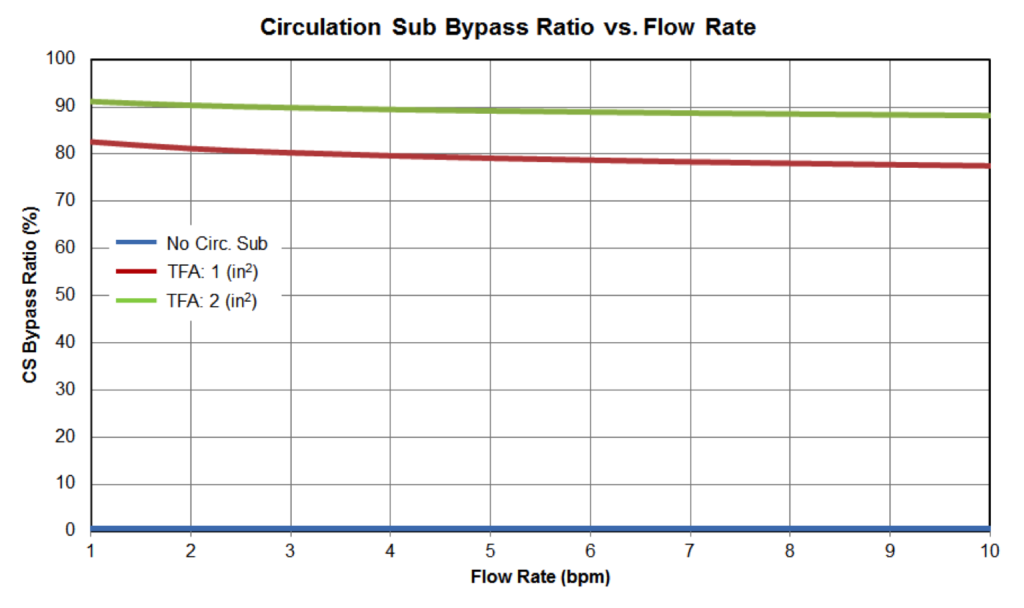
To study the sensitivity of flow rate on a circulation sub’s performance, 3 cases were chosen: one is without a circulation sub, and the other two have 1 (in2) and 2 (in2) of TFA, respectively. As we increase the flow rate from 1 to 10 (bpm), bypass ratios for both cases decrease. One might wonder why the bypass ratio decreases as flow rate increases. Does not the circulation sub play a bigger role in tougher conditions such as a high flow rate situation? Here is the reason behind the reverse change: the pressure drop across circulation sub nozzles (Path B) is proportional to the square of the flow rate, regardless of the rheological model. The frictional pressure loss along Path A is proportional to the flow rate to the power of 1.75 for Newtonian fluids in turbulent flow conditions. When the flow rate increases, it is relatively easier for fluid to flow along Path A than Path B. Therefore, at higher flow rates, the bypass ratio is smaller.

Figure 10: Circulation Sub Bypass Ratio vs Flow Rate

Figure 10: Circulation Sub Bypass Ratio vs Flow Rate

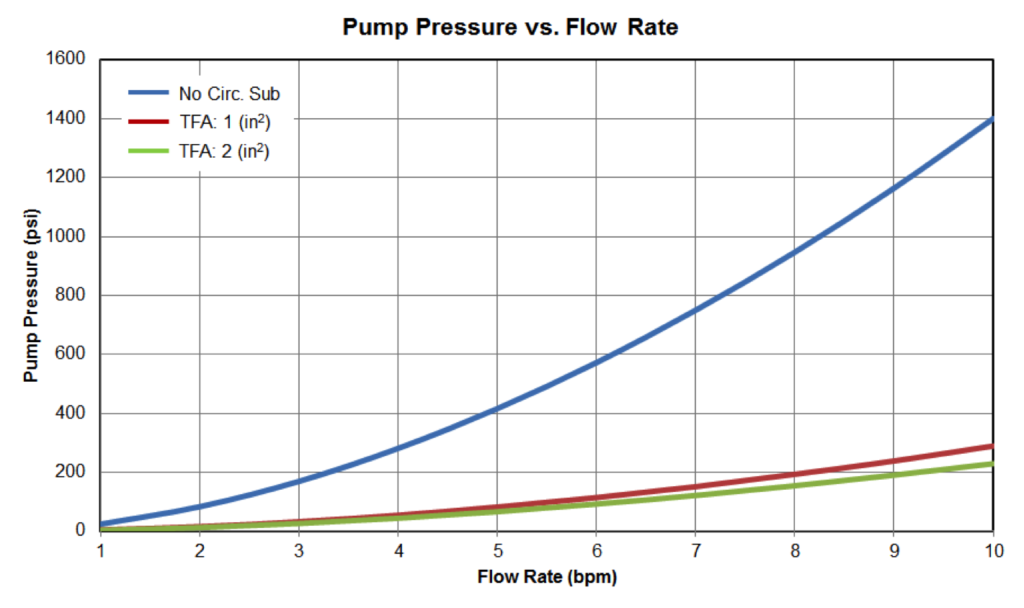
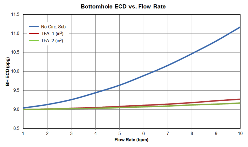
However, even with the slightly decreased bypass ratio at higher flow rate, the presence of a circulation sub greatly reduces pump pressure and bottom hole ECDs, as illustrated in Figure 11 and Figure 12. The benefits become more pronounced at higher flow rates. As noted before, the inclusion of a circulating sub makes a dramatic impact up to a certain TFA, in this case 1 square inch.

Figure11: Pump Pressure vs Flow Rate

Figure 11: Pump Pressure vs Flow Rate

Figure12: Bottom Hole ECD vs Flow Rate

Figure 12: Bottom Hole ECD vs Flow Rate

4. Effect of Viscosity

Since viscosity has a small impact on the analysis, the circulation sub’s nozzles have been changed to 2 x 10 (1/32in) for this portion of the analysis, which yields a TFA of 0.153 (in2) for our base case.

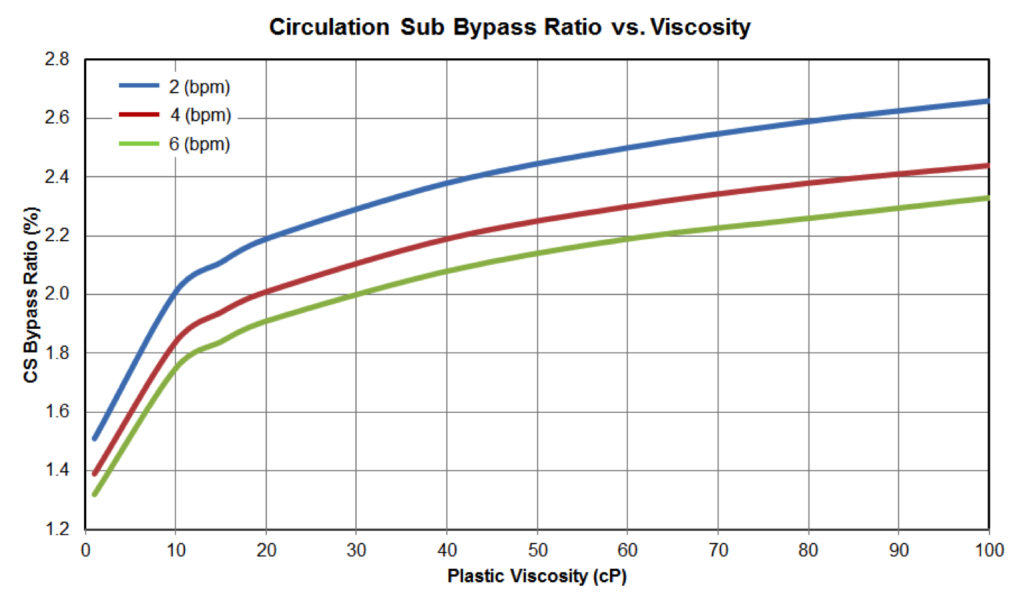
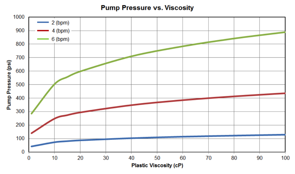
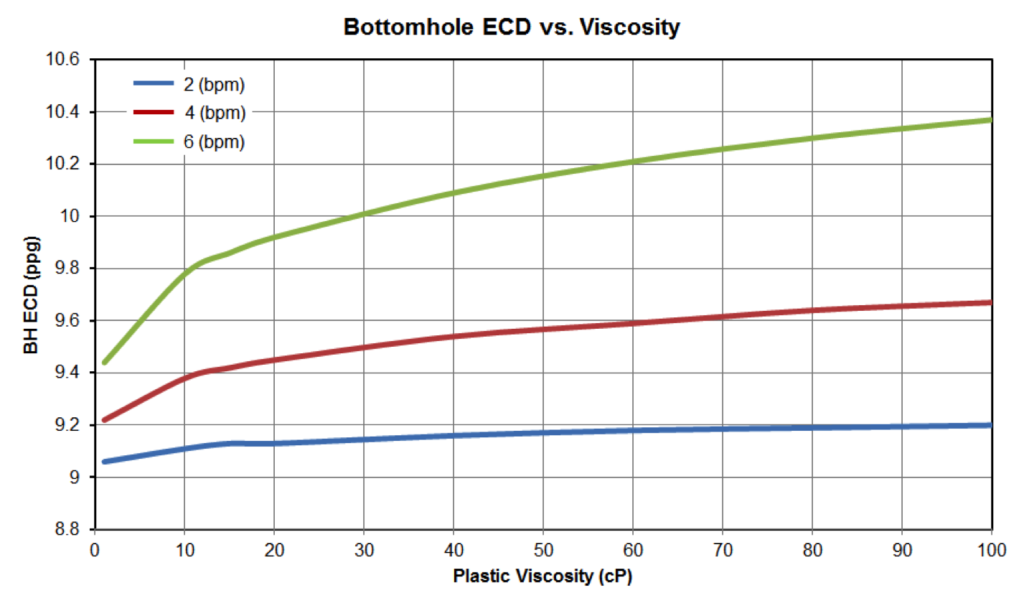
The flow split at a circulation sub is the result of flowing fluid seeking the path of least resistance and pressure balance. The frictional pressure loss along Path A is a function of fluid viscosity, density, flow rate and flow path geometry. If the flow is laminar, the pressure loss is proportional to the fluid viscosity for Newtonian fluid. The resistance of path B is dominated by the pressure drop across nozzles, where the viscous frictional effects are essentially negligible. As fluid viscosity increases, it is more difficult for fluid to flow through Path A. The bypass ratio will increase as illustrated by Figure 13. Both pump pressure and bottom hole ECD increase as fluid viscosity becomes higher. However, they would be much higher if no circulation sub is present.

Figure 13: Circulation Sub Bypass Ratio vs Fluid Viscosity

Figure 13: Circulation Sub Bypass Ratio vs Fluid Viscosity

Figure 14: Pump Pressure vs Fluid Viscosity

Figure 14: Pump Pressure vs Fluid Viscosity

Figure 15: Bottom Hole ECD vs Fluid Viscosity

Figure 15: Bottom Hole ECD vs Fluid Viscosity

5. Effect of Fluid Density

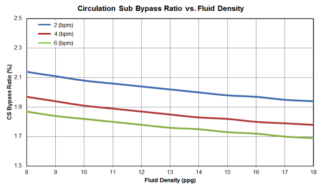
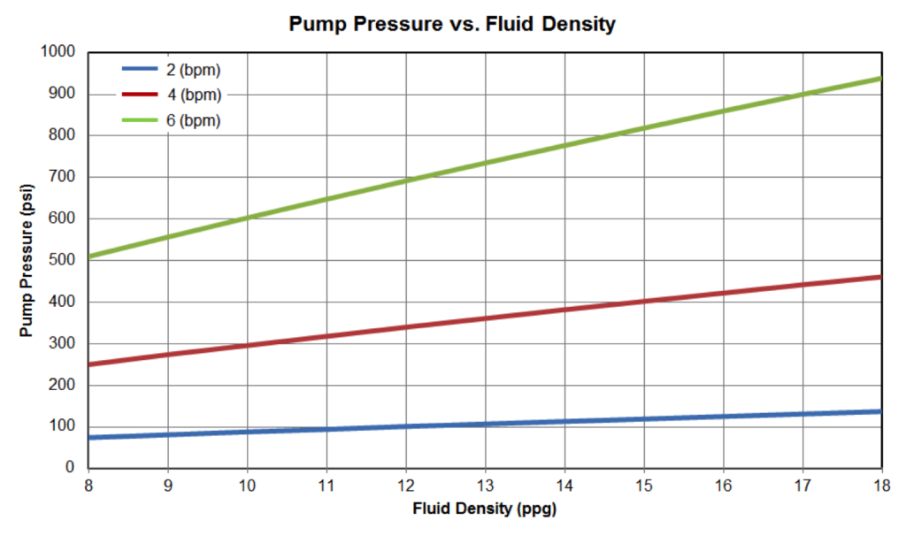
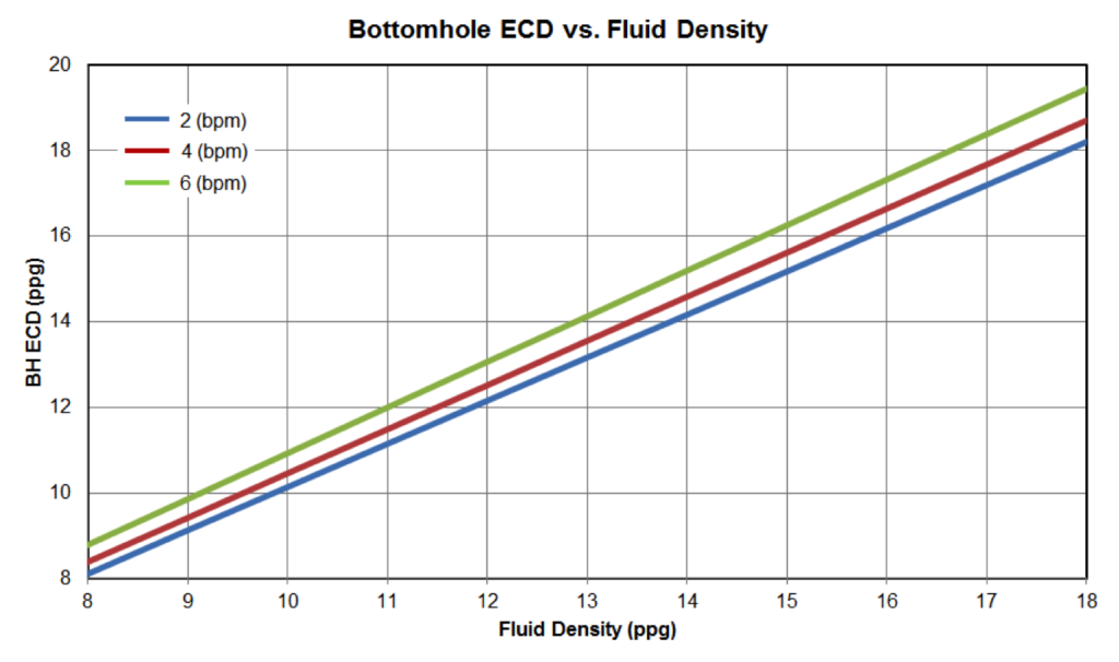
If the flow is turbulent, the pressure loss along Path A is proportional to the fluid density to the power of 0.75 for a Bingham plastic fluid. On the other hand, the pressure drop across Path B is proportional to the fluid density. As the fluid density increases, it is relatively more difficult for fluid to flow through Path B. The bypass ratio will decrease when fluid density increases as illustrated by Figure 16. The pump pressure increases as fluid density increases. The bottom hole ECD increases because both hydrostatic pressures and frictional pressure loses increase with greater fluid density.

Figure 16: Circulation Sub Bypass Ratio vs Fluid Density

Figure 16: Circulation Sub Bypass Ratio vs Fluid Density

Figure 17: Pump Pressure vs Fluid Density

Figure 17: Pump Pressure vs Fluid Density

Figure 18: Bottom Hole ECD vs Fluid Density

Figure 18: Bottom Hole ECD vs Fluid Density

The above case study is performed for a particular wellbore cleanup scenario. In order to have a better understanding of your particular case, it is recommended to use engineering software to take into account of well configurations and fluid properties to optimize circulation sub performance.

Circulation Sub Series—3: Case Study Part I of II


Case Study

Engineers may have some basic ideas on how to optimize the design parameters of a circulation sub to achieve their goals. For example, increasing the total flow area of a circulation sub will increase the bypass flow rate, reduce pump pressure, etc. This case study will quantify the impacts of various circulation sub parameters and fluid properties on pump pressure and ECD for a wellbore cleanup operation. We used a wellbore cleanup hydraulics software to perform this case study. Numerical methods are employed to obtain the correct flow split percentage at the location of the circulation sub. The flow split is obtained such that the summation of the frictional pressure losses inside the pipe below the circulation sub and in the annulus below the circulation sub should be equal to the pressure loss through the circulation sub nozzles.

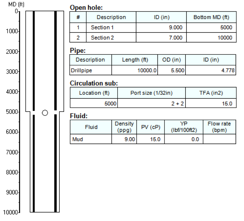
Figure 2 shows the wellbore configuration used for the example calculation. This is the basic case, from which we will perform sensitivity studies on each of 5 parameters. Note that the flow rate is left blank because it is run at several values for all stages.

Figure2: Example Case

Figure2: Example Case

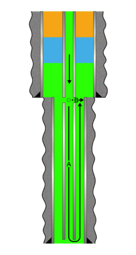
Figure3: Flow Paths

Figure3: Flow Paths

1. Effect of Total Flow Area (TFA)

Circulation sub’s adjustable nozzles enable you to define how the flow is split between the annulus and the pipe interiors. By adjusting the TFA of the circulation sub, you can control the amount of fluid that is diverted.

The flow split at a circulation sub is determined as the fluid chooses the path of least resistance. The rates of flow through the circulation sub and down the string are determined when these two flow paths reach a pressure balanced state. When fluid inside pipe travels to the circulation sub, it faces 2 choices. The first one is to flow downward through the pipe and up the annulus. Let us call this Flow Path A. The alternative path is sideways through the circulation sub’s nozzles. We will call this Flow Path B.

As illustrated by Figure 3, Flow Path A involves a long, but wide conduit, while Flow Path B is an array of short constrictions (nozzles).

The circulating fluid does not have a preference as which path to flow. When the fluid passes the circulation sub, it senses the resistances of both paths and chooses the split of fluid so that it yields an overall minimum resistance.

The frictional pressure loss, or flow resistance, along Path A is a function of fluid viscosity, density, flow rate, pipe ID, hole ID, pipe OD and flow path length. On the other hand, the resistance of Path B is dominated by the pressure drop across the nozzles, which is reversely proportional to the square of the TFA of those nozzles. As we increase the TFA of a circulation sub, it becomes much easier for fluid to flow through Path B. As a result, less fluid will flow through Path A and the frictional pressure losses in the lower pipe and annular sections will be reduced. Whatever the percentage of flow split, the pump pressure and ECD of the system are both reduced by the fluid bypass.

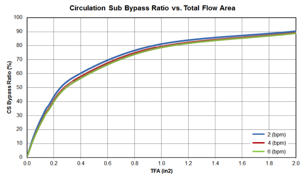
In our example, we increase the TFA from 0, representing a case of no circulation sub, to 2 (in2). Figure 4 shows increased fluid bypass ratios as the TFA increases for 3 flow rates, 2 (bpm), 4 (bpm) and 6 (bpm). The circulating sub bypass ratio is the percentage of flow exiting the string through the circulating sub nozzles, as opposed to the bit.

Figure4: Circulation Sub Bypass Ratio vs TFA

Figure4: Circulation Sub Bypass Ratio vs TFA

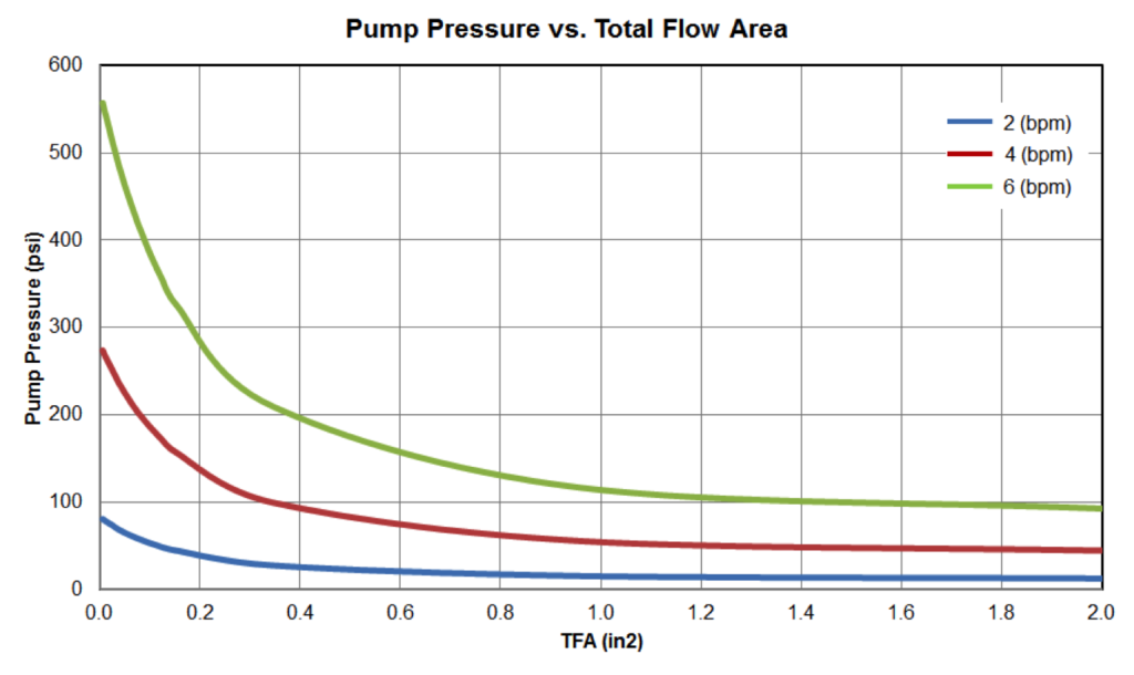
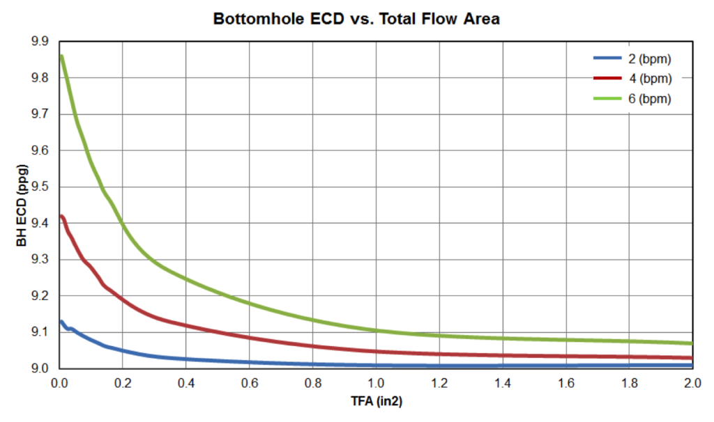
Accompanying these increased bypass ratios, both the pump pressure and bottom hole ECD reduce rapidly at beginning and more gradually later, as shown in Figure 5 and 6, respectively. The pump pressure is reduced by almost 80% when TFA is increased from 0 (in2) to 1 (in2) for a flow rate of 6 (bpm). Meanwhile, for the same flow rate, bottom hole ECD is reduced by 7.6%. Further increase of TFA from 1 (in2) to 2 (in2) yields only marginal reduction.

Figure5: Pump Pressure vs TFA

Figure5: Pump Pressure vs TFA

Figure6: Bottom Hole ECD vs TFA

Figure6: Bottom Hole ECD vs TFA

2. Effect of Circulation Sub Depth

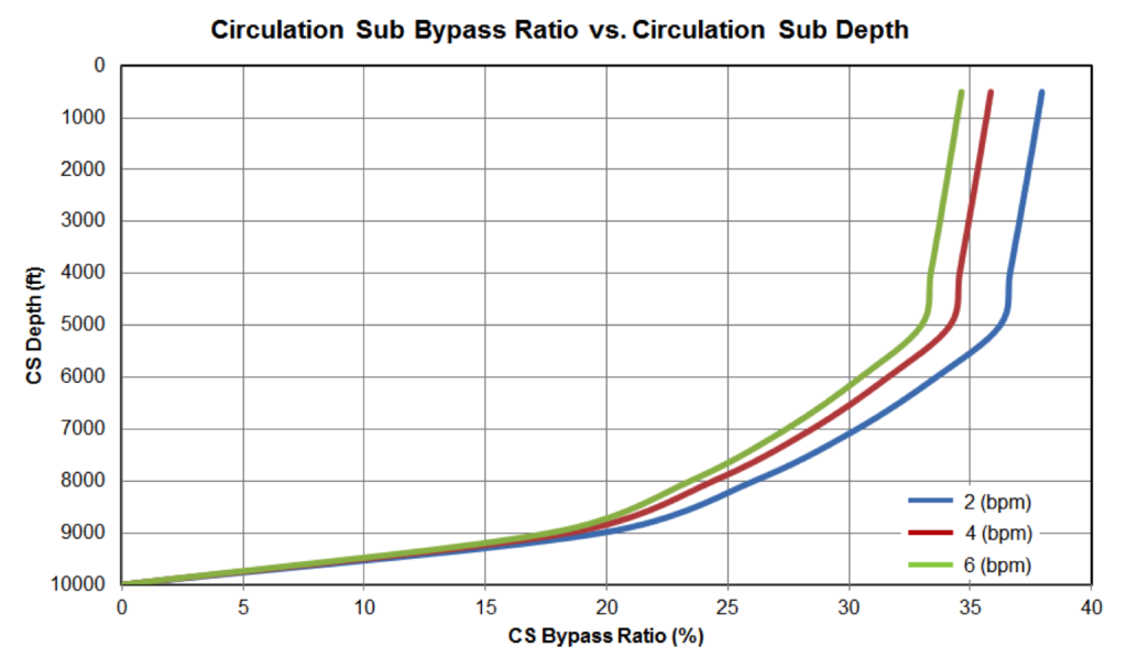
The location of the circulation sub affects the overall downhole hydraulics. A circulation sub establishes a communication path between fluid inside the pipe and fluid in the annulus. The closer a circulation sub is to surface, the greater the fluid bypass ratio is, because Flow Path A is getting longer and creates a higher frictional pressure drop. Figure 7 shows the bypass ratios at various circulation sub locations along the wellbore. As expected, if we place the circulation sub at the bottom of the pipe, it would have no effect on pump pressure or bottom hole ECD.

Figure7: Circulation Sub Bypass Ratio vs Circulation Sub Depth

Figure7: Circulation Sub Bypass Ratio vs Circulation Sub Depth

To take advantage of its unique characteristic for wellbore cleanup operations, a circulation sub is often placed at the depth where the wellbore geometry changes, such as the previous casing shoe. By increasing the pump rate, the hole section below the circulation sub with a smaller annular clearance can maintain the required fluid velocity from the downward split flow. The velocity of the fluid in the larger OD annulus above the circulation sub will see both the flow rate traveling down the string and through the sub’s ports, increasing the annular velocity to closely match that in the narrow clearance hole below.

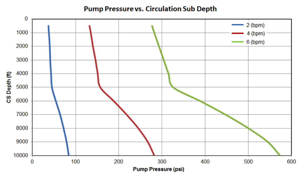
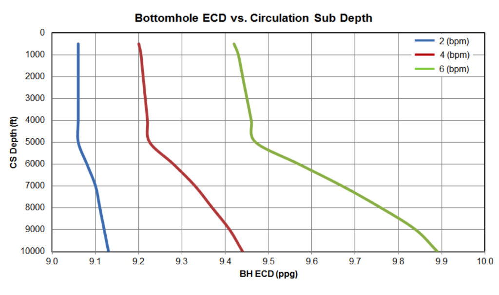
Greater reductions in both the pump pressure requirement and bottom hole ECD are achieved when a circulation sub is placed closer to surface, as seen in Figures 8 and 9. The pressure and ECD drops because less fluid is traveling through the narrower clearance section of the annulus.

Figure8: Pump Pressure vs Circulation Sub Depth

Figure8: Pump Pressure vs Circulation Sub Depth

Figure9: Bottom Hole ECD vs Circulation Sub Depth

Figure9: Bottom Hole ECD vs Circulation Sub Depth

Circulation Sub Series—2: Circulation Sub Uses in the Industry


How Do Circulation Subs Work?

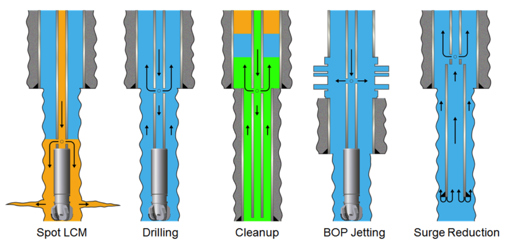
A circulation sub is useful in many applications such as spotting remediation fluids, drilling, wellbore cleanup, subsea blow out preventer (BOP) jetting and surge pressure reduction.

  1. Spot Remediation Fluids

Loss of circulation occurs when drilling fluids flow into formations instead of returning up the annulus. It is one of the most time-consuming and cost inflating events in drilling operations. The effective solution is to deploy, or spot, lost-circulation material (LCM) into the formation. Due to LCM’s nature to plug holes in the formation, it is difficult to pump LCM through the bottom hole assembly (BHA) components with restricted flowpaths, such as bits, downhole motors and measurement while drilling (MWD) tools. To spot aggressive LCM, circulating subs are typically placed above the BHA and divert LCM to the annulus without causing damage to the motor or other tools below.

  1. Drilling

Cuttings removal and managing downhole pressure are two critical elements while drilling, particularly in deepwater and extended-reach conditions. In directional wells, rock cuttings fall to the low side of the wellbore. As cutting beds build up and annular cuttings concentration increases, the frictional pressure loss between the drillpipe and wellbore increases. This could lead to more torque and drag related problems such as buckling, stick slip, vibration, and lockup events.

Adequate annular velocity is required to transport cuttings to surface. However, because of the presence of mud motors, MWD tools, and other flow restricting components, it is often difficult to achieve annular velocities high enough to effectively transport cuttings without over spinning the motor. The narrow passage inside the BHA creates higher pressure losses, which could result in a high pump pressure requirement.

With pump rates hampered either by BHA restrictions or by equivalent circulating density (ECD) window considerations, a circulation sub, typically placed above the BHA, is often a convenient and simple solution. By bypassing the BHA and preventing motor overrun, a circulation sub can reduce wear on the motor and increase its reliability and operating hours. ‘Bottoms-up’ circulating time is greatly reduced and hole cleaning is improved. A percentage of flow to the drill bit is retained, which can be adjusted, keeping BHA components lubricated.

In summary, a circulating sub enables the rig to maintain a higher annular velocity, reduces pump pressure requirements, and reduces ECD at the bottom of the hole.

  1. Wellbore Cleanup

A clean well is essential prior to running expensive and sensitive completion strings or other debris sensitive equipment. The first step to ensure an optimum completion is to remove leftover drilling fluid residue and casing debris. This requires that the drilling mud be changed out with solids-free completion fluids. Completion fluid displacement involves multiple fluids sequenced in circulation.

Multiple fluids are used in wellbore cleanup operations, including drilling mud, water, spacers, pills, and flushes. Spacers are viscous fluids used to aid in the displacement or removal of other fluids. Pills are small volumes of specially prepared fluid designed to accomplish a specific task, such as lifting debris from a wellbore or removing scale on the internal diameter (ID) of casing. Flushes are used to prepare for or assist in production from the producing zone.

In wellbore cleanup operations, similar to a drilling scenario, a circulation sub permits an increased flow rate by opening flow paths to the annulus above the flow-restricting annular sections with smaller hole ID or large outer diameter (OD) string components. Bypassing the smaller annular sections allows the maximum amount of fluid to be directed to the annulus, thus boosting annular velocity for more effective wellbore cleanup above the circulation sub location and lowering the pump pressure. These operations can be optimized by adjusting the port sizes of circulation sub so that the desired downward flow rate is achieved to clean up the hole sections below with restricted annular clearances.

  1. Blowout preventer (BOP) stack jetting

Circulation subs are also used to hydroblast the subsea wellhead or BOP cavities. The nozzles, or ports, on the circulation sub direct fluid out to the BOP stack and create jet impact forces that thoroughly dislodge junk and debris.

  1. Surge pressure reduction

During casing or liner running, a circulation sub can be used in conjunction with auto-fill float equipment. Normally located on drillpipe immediately above the liner, the ports of the circulation sub allow the fluid trapped in the liner access to the larger annulus between drillpipe and previous casing, in addition to the flowpath through the restrictive drill pipe ID. The auto-fill float equipment and circulation sub establish 2 places of fluid communication between pipe interior and annulus. Fluid displaced by the string seeks the least resistant flowpath. A circulation sub opens a less restrictive flowpath, which helps to reduce the surge pressure.

These circulation sub applications are illustrated in Figure 1.

Applications of Circulation Sub

Figure1: Applications of Circulation Sub

Future Blogs

The third and fourth articles will discuss the numerical analysis used and the results on changes in the critical variables that affect the flow split created by a circulating sub. These variables are:

  • Total Flow Area (circulating sub ports)
  • Depth of the Circulating Sub
  • Flow Rate
  • Fluid Viscosity
  • Fluid Density

Circulation Sub Series—1: Circulation Subs Introduction


Pegasus Vertex Inc. (PVI) is pleased to introduce the first of four blogs related to circulating subs. PVI will also present this topic at the 2017 ATCE conference as SPE-187151-MS. Please follow along today as we introduce the definition of a circulating sub, general uses in the oilfield, and the numberical simulation study related to key variables affecting circulating subs’ performance downhole.

Introduction

Circulation subs are downhole tools designed to create an additional flowpath from the pipe to the annulus. The percentage of fluid that exits the string instead of traveling down to the bit or shoe depends not only on the size of the circulation sub ports, but also upon the density and rheology of the fluid, the flow rate, and the sub’s position in the string.

These four blog articles will take a thorough look at the above-mentioned variables that affect the percentage of fluid travelling the two flowpaths when using a circulation sub, along with their impact on pump pressure and equivalent circulating density (ECD). We will describe the various common operations and uses of circulation subs. The flow rate, circulation sub’s position in the string, fluid density, fluid rheology, and total flow area out of the circulating sub were analyzed to determine the degree of flow split, pump pressure, and ECD changes.

Graphical representations of outputs will be shared to illustrate the results of changing variables when using circulating subs. The sensitivity of the flow split between fluid traveling down the string vs. into the annulus when changes occur in the total flow area, depth of the circulation sub, flow rate, fluid viscosity, and density are discussed. These variables are also used to evaluate the impact on each other, with a focus on the resulting pump pressure and bottom hole ECD.

What Is a Circulation Sub?

A circulation sub is a downhole tool designed to control flow between the pipe and annulus. Once activated, the downward flow through pipe at the circulation sub location will be split. Some of the circulating fluid will flow through the sideway ports to the annulus between the wellbore and pipe, either downward or upward, depending on the operation.

One of the common ways to activate circulation through the circulating sub is to drop a ball in the drill string and pump it down. After the ball lands in the pre-designed seat in the sub, pump pressure is applied. A pin will be sheared that consequently allows the sleeve to shift and hence open the circulation ports to allow fluid flow sideway into the annulus.

Next Blog

The second blog article will introduce the common uses of circulating subs in the oilfield, including:

  • Spotting Remediation Fluids
  • Drilling
  • Wellbore Cleanup
  • Blowout Preventer (BOP) Stack Jetting
  • Surge Pressure Reduction

A Memento from the Past: Keep Calm and Carry On


The wear and tear of our clothing is not caused by wearing them, but by washing them in washing machines instead. Many of my tennis shirts which I have been wearing for more than a decade have faded in color here and there and the fabric has thinned out over time. Still, I have no problem wearing these shirts on the tennis courts.

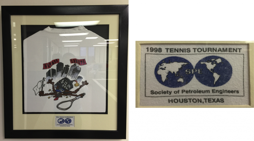
Every fall, the SPE Gulf Coast Section (GCS) holds an annual tennis tournament where they give out t-shirts to every registered player. I have been an active participant of this event and have collected close to 20 shirts over the years. The designs have varied in some way, but have maintained the same style, a cartoon on the back depicting the theme of the year.

Among these t-shirts is the one I got from the tennis tournament held in 1998. Every time I see this shirt, I cannot help but let out a long sigh. Last month, I decided that this particular T-shirt should be treated as a relic, a piece of history that should be hung up in a museum. So I got it framed and hung it up on our office wall.

SPE_Tennis_T-shirt

That year, I was a mechanical/software engineer with Maurer Engineering, developing drilling software for DEA-44 (Drilling Engineer Association’s horizontal drilling joint-industry project). $12/bbl must have been the lowest oil price in 1998 right before SPE held their tennis tournament on October of that year. I don’t recall SPE ever making a T-shirt showing the record high oil price in the 2000s. Every time I wear this 1998 shirt to play tennis, my friends and I get a good laugh from it since most of them are involved with the industry and have all been a part of the oil-price roller coaster ride. The heydays of the drilling industry have helped us grow, and we have survived (or at least try to do so) in an era like the one we’re living through now.

In early 2015 I told my team members that the low oil price was an opportunity for us to shift our focus to development. Now, being already the 3rd quarter of 2016, we are still stumbling on the downturn. But then again, who in this industry isn’t? Robert Louis Stevenson once said, “Judge each day not by the harvest you reap, but by the seeds you plant.” This is probably not our time for reaping, but for planting seeds instead.

I used to carry this oil price on my back, but now I have placed it on the wall, knowing that some things are bound to be out of my control. I do my best within my means, and I have to make peace with those things I have no control over.

The Significance of Cleanups: What a difference it makes!


Picture this: a filthy driveway that has not been washed in months, covered in dead leaves, mud, and dirt. All those lifeless bits of wilted foliage and dirt have mixed resulting in gunk being stuck to the concrete driveway. So what do you do? Dig through your garage, pull out the pressure washer and get to work! Whether it is a dirty driveway or a wellbore, in order for all things to serve their purpose, we must make sure we are able to clean out the mess and residue, to get us through to our next step.

Successful well completions rely on a lot of factors. As mentioned before, one main aspect is maintaining a clean wellbore, free of debris or any other fluid residue that has been left behind due to the nature of drilling fluids. Whether it is a dirty driveway or a wellbore, the process of cleaning highly increases the chances for us to foresee what is to come next. Enter CleanMax, the next generation of wellbore cleanup.

Avoiding mishaps is quintessential for any project we take upon ourselves. When it comes to operations, failure to conduct wellbore cleanups could lead to potential failed completions, not to mention the high costs associated with it. It is essential that we not take risks when it comes to this and use the tools that we have at hand to accurately conduct successful wellbore cleanups and safer operations. One of our most recent software, CleanMax, does just that and more. We have created the go-to software that meets the needs for both service companies and operators, helping minimize spacer interfacing and reducing rig time, pill volumes, and filtration costs.

CleanMax - Wellbore Cleanup Software

We are all cognizant that drilling comes with its complexities. During this challenging time in our industry, we have had to make crucial decisions when it comes to getting the job done efficiently while keeping costs in mind.  At PVI, we know this all too well. “How?” you may ask, and the answer is pretty straightforward: because we are the ones who create the tools to turn this into a sophisticated, yet simple process (that’s our slogan!). We are your eyes when it comes to successful drilling completions!

For more information about CleanMax and CleanMax+, please visit:

http://www.pvisoftware.com/wellbore-cleanup-software.html