1. Wear Mechanism
The casing wear model applied in CWPRO (casing wear prediction software developed by PVI) assumes that the metal volume worn away in a wear groove section is proportional to the frictional energy transmitted to the casing by a rotating tool joint as shown in Figure 2 in the Casing Wear Series – 1: Causes.
The transmitted frictional energy is defined in this formula:
Where:
E = Frictional Energy, lb-ft
μ = Friction factor, dimensionless
SF= Side force on tool joint per foot, lbf/ft
SD = Sliding distance traveled by the tool joint against casing wall, in
The volume of casing wall removed per foot in time t hours is mathematically expressed in the equation:
Where:
WV = Casing wear volume per foot, in3/ft
WF = Wear factor, E-10psi
SFdp = Side force on drill pipe per foot, lbf/ft
Dtj = Tool joint OD, in
N = Rotary speed, rpm
t = Rotating time, hr
The definition of wear factor is the ratio of friction factor to specific energy, which is the amount of energy required to remove a unit of steel. The unit for wear factor is E-10psi-1; therefore, when a wear factor is reported as 8, the actual value used in casing wear calculation is 8E-10psi-1.
Quite a few experiments were conducted to find the casing wear factors under different mud systems, tool joint materials, casing interior and drill string protectors. Among them, Maurer Engineering Inc. conducted joint-industry project DEA-42. It was reported that more than 300 laboratory tests were performed under DEA-42 to determine the wear factors for various drilling conditions.
For a typical water-based mud, WF can vary as follows:
Normal or low: 3 – 7
Medium: 8 – 13
High: 14 – 20
WF above 20 can be considered as very high and may cause severe casing damage.
2. Wear Geometry
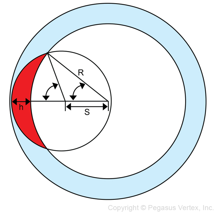
A typical wear groove is shown in the following figure.
The relationship between wear depth and casing wear volume is:
Where:
WV = casing wear volume per foot, in3/ft
h = wear depth, in
r = tool joint outer radius, in
R = casing inner radius, in
S = R - (r - h), in
P = (R + r + S) / 2, in
3. Software
Based on the R & D results from the past two decades, PVI developed CWPRO, software that enables us to understand the casing wear phenomenon and accurately predict casing wear before the drilling operation or perform a post-drilling analysis.
CWPRO is a comprehensive casing wear prediction software with built-in torque and drag function. For every incremental drilling interval, the amount of energy transferred from drill pipe to casing is calculated. Accumulative wear and wear depth are first obtained and then the burst and collapse strength of the worn casing can be assessed.
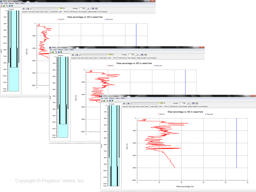
Being a time-dependent incident, casing wear deepens as we drill deeper. Figure 2 shows the sequence of drilling and corresponding wear profile along the previously set casing.


