We are going to study on the 5 parameters affecting casing standoff.
1. Well trajectory
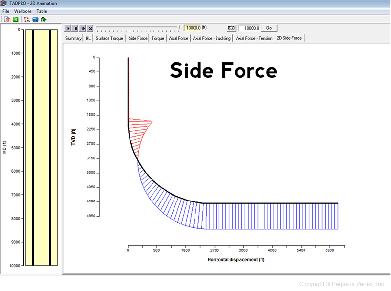
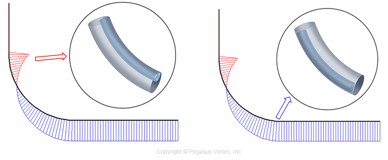
Well trajectory is expressed in terms of survey data, consisting measured depth, inclination and azimuth angles. It defines the shape of the well path and thus has great impact on the direction and magnitude of the side forces that pull the casing string to the wellbore. Fig. 5 shows the magnitude and direction of the side force distribution on a casing in a horizontal well.
For a casing section in a build-up or horizontal section of wellbore, the weight of pipe pulls the casing toward to the lower side of hole. The blue lines indicate that the casing touches the lower side of wellbore. The upper section of the casing string has to sustain the weight of lower casing sections. This creates tension force along the casing string. Wellbore doglegs cause the resultant force to pull the casing toward the upper side of the hole, as indicated by the red lines. Therefore, casing string in a deviated or horizontal well always touches the wellbore, upper or lower side.
Generally speaking, horizontal or extended reach wells require more support from centralizers to maintain a good standoff profile.
2. Casing size and weight
Casing weight determines the gravitational force which pulls the pipe toward the lower side of the borehole. The heavier the casing string is, more or stronger centralizers are required.
3. Fluids inside casing and in annulus
The buoyancy force calculation is further complicated by the multi-fluid configuration during a cementing job. When heavy cement slurries are inside the casing and light drilling mud in the annulus, the effective weight of casing is at its greatest. On the other hand, when cement slurries are in place and displacement fluid inside the casing, the buoyancy is at its peak and the effective weight of the pipe is the least.
When we design the centralizer placement for the scenario of cement slurries in place, it favors us to have less effective casing weight, pulling the casing string downward; but when the cement slurries are inside the casing during the displacement, the lower standoff could cause mud channeling problems. It is better to study standoff for all the situations.
4. Centralizer properties
Not all centralizers are created equal. Centralizer manufacturers are striving to improve the performances of their products.
For solid centralizers including mold-on type, the blade OD is the key parameter as far as the casing centralization is concerned.
For bow-spring centralizers, the restoring force is the measurement of the strength of a centralizer. It is defined as the side force to deflect the bow by 1/3 or its original height.
5. Centralizer placement
Once the well is planned, casing designed, cementing procedure prepared and centralizer type selected, we do not have many options other than placing the centralizers strategically to achieve the desired standoff. However, this is also a great leverage.
Poor spacing will result in poor standoff even with the best centralizers in the market.


