Case Study
Engineers may have some basic ideas on how to optimize the design parameters of a circulation sub to achieve their goals. For example, increasing the total flow area of a circulation sub will increase the bypass flow rate, reduce pump pressure, etc. This case study will quantify the impacts of various circulation sub parameters and fluid properties on pump pressure and ECD for a wellbore cleanup operation. We used a wellbore cleanup hydraulics software to perform this case study. Numerical methods are employed to obtain the correct flow split percentage at the location of the circulation sub. The flow split is obtained such that the summation of the frictional pressure losses inside the pipe below the circulation sub and in the annulus below the circulation sub should be equal to the pressure loss through the circulation sub nozzles.
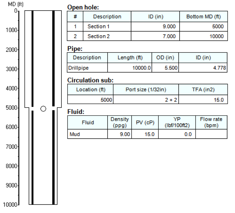
Figure 2 shows the wellbore configuration used for the example calculation. This is the basic case, from which we will perform sensitivity studies on each of 5 parameters. Note that the flow rate is left blank because it is run at several values for all stages.
1. Effect of Total Flow Area (TFA)
Circulation sub’s adjustable nozzles enable you to define how the flow is split between the annulus and the pipe interiors. By adjusting the TFA of the circulation sub, you can control the amount of fluid that is diverted.
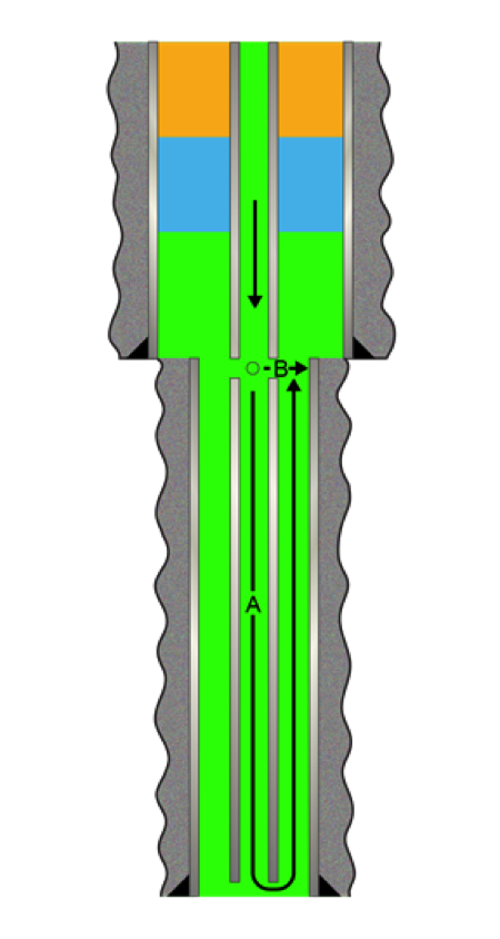
The flow split at a circulation sub is determined as the fluid chooses the path of least resistance. The rates of flow through the circulation sub and down the string are determined when these two flow paths reach a pressure balanced state. When fluid inside pipe travels to the circulation sub, it faces 2 choices. The first one is to flow downward through the pipe and up the annulus. Let us call this Flow Path A. The alternative path is sideways through the circulation sub’s nozzles. We will call this Flow Path B.
As illustrated by Figure 3, Flow Path A involves a long, but wide conduit, while Flow Path B is an array of short constrictions (nozzles).
The circulating fluid does not have a preference as which path to flow. When the fluid passes the circulation sub, it senses the resistances of both paths and chooses the split of fluid so that it yields an overall minimum resistance.
The frictional pressure loss, or flow resistance, along Path A is a function of fluid viscosity, density, flow rate, pipe ID, hole ID, pipe OD and flow path length. On the other hand, the resistance of Path B is dominated by the pressure drop across the nozzles, which is reversely proportional to the square of the TFA of those nozzles. As we increase the TFA of a circulation sub, it becomes much easier for fluid to flow through Path B. As a result, less fluid will flow through Path A and the frictional pressure losses in the lower pipe and annular sections will be reduced. Whatever the percentage of flow split, the pump pressure and ECD of the system are both reduced by the fluid bypass.
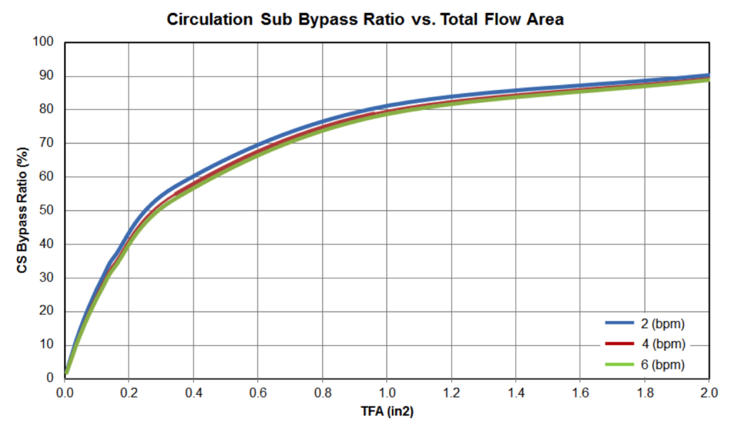
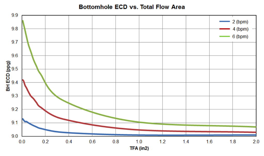
In our example, we increase the TFA from 0, representing a case of no circulation sub, to 2 (in2). Figure 4 shows increased fluid bypass ratios as the TFA increases for 3 flow rates, 2 (bpm), 4 (bpm) and 6 (bpm). The circulating sub bypass ratio is the percentage of flow exiting the string through the circulating sub nozzles, as opposed to the bit.
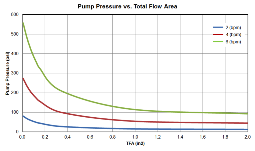
Accompanying these increased bypass ratios, both the pump pressure and bottom hole ECD reduce rapidly at beginning and more gradually later, as shown in Figure 5 and 6, respectively. The pump pressure is reduced by almost 80% when TFA is increased from 0 (in2) to 1 (in2) for a flow rate of 6 (bpm). Meanwhile, for the same flow rate, bottom hole ECD is reduced by 7.6%. Further increase of TFA from 1 (in2) to 2 (in2) yields only marginal reduction.
2. Effect of Circulation Sub Depth
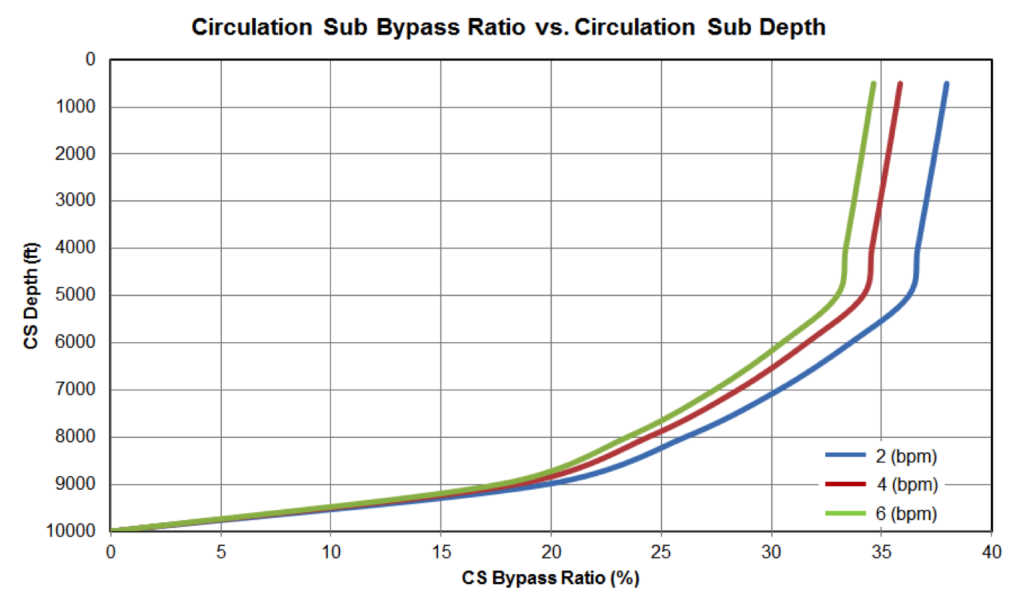
The location of the circulation sub affects the overall downhole hydraulics. A circulation sub establishes a communication path between fluid inside the pipe and fluid in the annulus. The closer a circulation sub is to surface, the greater the fluid bypass ratio is, because Flow Path A is getting longer and creates a higher frictional pressure drop. Figure 7 shows the bypass ratios at various circulation sub locations along the wellbore. As expected, if we place the circulation sub at the bottom of the pipe, it would have no effect on pump pressure or bottom hole ECD.
To take advantage of its unique characteristic for wellbore cleanup operations, a circulation sub is often placed at the depth where the wellbore geometry changes, such as the previous casing shoe. By increasing the pump rate, the hole section below the circulation sub with a smaller annular clearance can maintain the required fluid velocity from the downward split flow. The velocity of the fluid in the larger OD annulus above the circulation sub will see both the flow rate traveling down the string and through the sub’s ports, increasing the annular velocity to closely match that in the narrow clearance hole below.
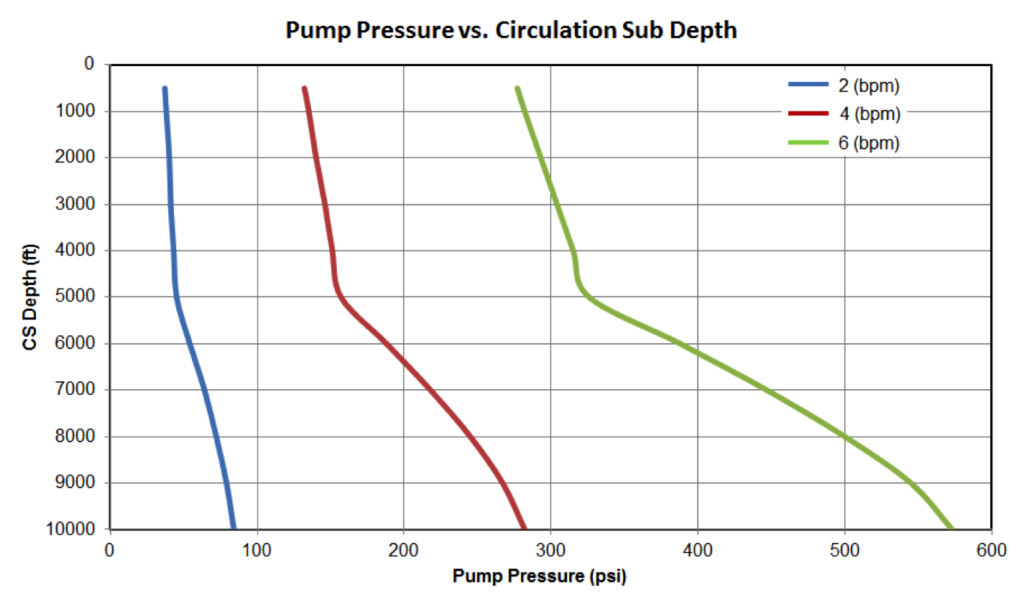
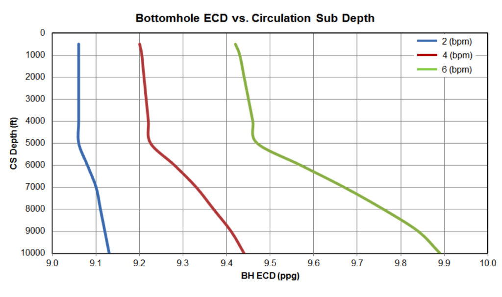
Greater reductions in both the pump pressure requirement and bottom hole ECD are achieved when a circulation sub is placed closer to surface, as seen in Figures 8 and 9. The pressure and ECD drops because less fluid is traveling through the narrower clearance section of the annulus.

